ADNK-3043-ND24 Avago Technologies US Inc., ADNK-3043-ND24 Datasheet
ADNK-3043-ND24
Specifications of ADNK-3043-ND24


Related parts for ADNK-3043-ND24


ADNK-3043-ND24 Summary of contents
Page 1
... ADNK-3043-ND24 2.4GHz RF Wireless USB Optical Mouse Designer’s Kit Design Guide Introduction This design guide describes the design of a low power consumption optical mouse using the Texas Instrument MSP430F1222 microcontroller, the Avago ADNS-3040 optical sensor and a Nordic nRF2402 2.4 GHz transmit- ter ...
Page 2
... Optical Mouse Sensor NCS TI MSP430F1222 Microcontroller Quadrature Z Optics Signals Left Button Wheel Button Right Button Figure 1. ADNK-3043-ND24 Reference Design Mouse functional Block Dia- LED Lens Figure 2. Illustration of Optical Navigation technology MAX1722 Boost Regulator Control RF Board and Data Image Array Lens Surface ...
Page 3
Z-Wheel The motion of Z-wheel is detected using the quadrature signal generated by optical sensors. Two phototransistors are connected in a source-follower configuration forming Channel A and Channel B. An infrared LED shines, causing the phototransistors to turn on. In ...
Page 4
Serial Peripheral Interface (SPI) The MSP430F1222 provides a dedicated hardware-based Serial Peripheral Interface (SPI). The three-wire interface supports byte serial communication in either Master or Slave mode. In this reference design the MSP430F1222 always acts as the master and initiates ...
Page 5
... Figure 4. Exploded view of the ADNS-3040 optical tracking engine Caution: The lens is not permanently attached to the sensor and will drop out of the assembly Disassemble the ADNK-3043-ND24 Unit The ADNK-3034-ND24 comprises of the plastic mouse casing, a main printed circuit board (PCB), lens, buttons, and a 2.4 GHz RF daughter card, and a 2.4 GHz USB receiver dongle ...
Page 6
... See Appendix D for details. Reference Design Documentation – Gerber File The Gerber File presents detailed schematics used in ADNK-3034-ND24 in PCB layout form. See Appendix C for more details. Overall circuit A schematic of the overall circuit is shown in Appendix A ...
Page 7
LEFT Button Port 1 Interrupt WHEEL Button Port 1 Interrupt RIGHT Button Port 1 Interrupt Scroll Wheel Module Periodic TIMER_A1 (1) Turn Wheel LED ON Interrupt (2) Read scroll wheel position (every 2 msec) (3) Turn Wheel LED OFF (4) ...
Page 8
HLMP-ED80 8 0.01uF C106 1uF C105 ...
Page 9
R203 Vdd 5 C210 C205 C206 10uF 1nF 10nF Antenna C201 1pF C213 L201 3.6nH 1.5pF C202 1pF L203 22nH 22pF Figure A2. Schematic Diagram of RF Transmitter Daughter Board 9 Vdd/ 22pF C208 C207 22pF X20116MHz R201 1M Vdd/ ...
Page 10
IREF 19 VSS 20 VDD 21 VSS 22 PWR_UP 23 VDD 24 R21833k R21733k R21633k R21533k R21433k R21333k R21233k R21133k R21033k 10 GND XC1 12 XC2 11 VSS 10 DVDD 9 DATA 8 CLK1 7 2 ...
Page 11
Appendix B: Bill of Materials (BOM) Table B1. BOM for Components Shown on Schematic: Sensor and Microcontroller Main Board Part Type Optical Sensor Device Optical Sensor LED Optical Sensor Lens Optical Sensor Clip Microcontroller DC/DC Converter Z LED Z Encoder ...
Page 12
BOM for nRF2402 Reference Design: RF Board Table B2. BOM for Components Shown on Schematic: RF Transmitter Daughter Board Part Description Resistor (0402) Resistor (0402) Resistor (0402) Ceramic Capacitor, 50v X7R (0402) Ceramic Capacitor, 50v X7R (0402) Ceramic Capacitor, 50v ...
Page 13
Table B3. BOM for Components Shown on Schematic: USB Dongle Part Description Capacitor (C0G (NP0 ±5 %, 0603) Capacitor (C0G (NP0 ±5 %, 0603) Capacitor (X7R ±10 %, 0603) Capacitor (X7R ±10 ...
Page 14
Appendix C: Base Plate Feature Figure C1. Illustration of base plate mounting features 14 ADNS-3120-001 LEN RECESS ADNS DIMENSIONS: DIMENSIONS: 31.5 x 17.0 mm 31.5 x 17.0 mm KEY PYRAMID KEY PYRAMID FEATURE: FEATURE: 2.50mm HEIGHT MAX. 2.50mm HEIGHT MAX. ...
Page 15
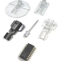
Appendix D: Sectional view of PCB assembly Sensor PCB Lens/Light Pipe Base Plate Surface Figure E1: Sectional view of PCB assembly highlighting all optical mouse components (optical mouse sensor, clip, lens, LED, PCB, and base plate). Appendix E: Receiver dongle ...
Page 16
... Wireless LED Mouseb. USB Mouse Set Dongle ADNS-3040 LED Mouse Sensor ADNS-3120-001 LED Mouse Trim Lens Plate ADNS-2220 LED Clip HLMP-ED80-PS000 Light Emitting diode ADNK-3043-ND24 Includes Documentation and Support Files for ADNK-3043-ND24 CD Documentation ADNK-3043-ND24 Optical mouse Designer’s kit Design Guide Hardware Support Files a ...