CL4490-1000-232 Laird Technologies, CL4490-1000-232 Datasheet - Page 17
CL4490-1000-232
Manufacturer Part Number
CL4490-1000-232
Description
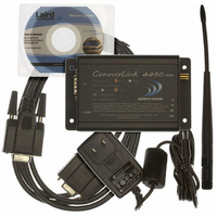
TXRX 900MHZ RS232 1W W/ANT DB9
Manufacturer
Laird Technologies
Series
Connexlink™r
Specifications of CL4490-1000-232
Function
Transceiver
Modulation Or Protocol
FHSS, FSK
Frequency
902MHz ~ 928MHz
Applications
General Purpose
Interface
RS-232
Sensitivity
-99dBm
Power - Output
1000mW
Data Rate - Maximum
76.8 kbps
Features
RS 232 Interface
Voltage - Supply
7 V ~ 18 V
Package / Case
Module
Wireless Frequency
900 MHz
Interface Type
RS-232, RS-485
Board Size
121 mm x 70 mm x 30 mm
Modulation
FHSS, FSK
Security
1 byte System ID, DES
Operating Voltage
100 V to 120 V
Output Power
1000 mW
Antenna
Dipole
Lead Free Status / RoHS Status
Contains lead / RoHS non-compliant
Lead Free Status / RoHS Status
Contains lead / RoHS non-compliant, Lead free / RoHS Compliant


CL4490 User’s Manual
4.1.1.2 Optional Settings
10/3/2005
Max Transmit Retries (For Clients and Servers in Point-to-Point networks only): This
value represents the maximum number of times a particular data packet will be transmitted
unsuccessfully, or without an acknowledgement, before the CL4490 discards the packet.
The default value is 16 attempts. If communication is lost and the Client’s Link LED is on, try
increasing this value in small increments until communication is reestablished.
Note: This value is always associated to Client radios and Server radios in Point to Point
Mode. The valid range of values for this field is 2 to 255.
Broadcast Attempts (For Servers in Point-to-Multipoint networks only): This value
represents the number of times a data packet will be transmitted by the Server CL4490. The
default value is 4 attempts. If communication is lost and the Clients’ Link LED is on, try
increasing this value in small increments until communication is reestablished. The valid
range of values for this field is 2 to 255
System Identification: A number from 0 to 256 that provides added security to each
independent network of CL4490 units. The System ID is used in conjunction with the
Channel Number and serves as an RF password to maintain secure transfers of data. The
combination of the Channel Number and System ID must be unique to each network of
CL4490s to establish communication. Multiple Servers in the same coverage area must be
programmed with different Channel Numbers to prevent inoperability of the networks. The
System ID will not prevent inoperability that occurs from locating multiple Servers with the
same Channel Number in the same coverage area.
Important Note: Separate Collocated CL4490 networks must operate on different
Channel Numbers. All units in a given CL4490 network must have identical Channel
Numbers and System IDs.
Data Encryption Key: Encryption is the process of encoding an information bit stream to
secure the data content. The DES algorithm is a common, simple and well-established
encryption routine. An encryption key of 56 bits is used to encrypt the packet. The receiver
must use the exact same key to decrypt the packet; otherwise garbled data will be produced.
Destination Address: The MAC Address of the remote CL4490 in a Point-to-Point network.
Used to optimize Point-to-Point communications by utilizing RF Acknowledgement.
Firmware Version: Displays the CL4490’s firmware version.
MAC Address: A unique 6 Byte, IEEE 802.3 Ethernet address assigned by AeroComm to
each CL4490.
Data Encryption: Enables the Data Encryption Key. All CL4490s in the same network must
have the same encryption setting.
RTS Enable: Enables the Request To Send control line. When enabled, enables Hardware
Flow Control. Refer to Section 2.3 Hardware Flow Control.
Parity: Needs to be enabled if host requires even or odd parity and 8 data bits. This is
considered as 9-bit mode. Note: Enabling Parity cuts the overall throughput into half.
17
Related parts for CL4490-1000-232
Image
Part Number
Description
Manufacturer
Datasheet
Request
R

Part Number:
Description:
TXRX 900MHZ RS232 1W W/ANT'S DB9
Manufacturer:
Laird Technologies
Datasheet:

Part Number:
Description:
TXRX 900MHZ RS485 1W W/ANT DB9
Manufacturer:
Laird Technologies
Datasheet:

Part Number:
Description:
TXRX USB 900MHZ 200MW W/ANTENNA
Manufacturer:
Laird Technologies
Datasheet:

Part Number:
Description:
TXRX 900MHZ RS485 1W W/ANT'S DB9
Manufacturer:
Laird Technologies
Datasheet:

Part Number:
Description:
TXRX 900MHZ PRO 1W W/ANT'S DB9
Manufacturer:
Laird Technologies
Datasheet:

Part Number:
Description:
WiFi / 802.11 Modules & Development Tools RS232 Client config
Manufacturer:
Laird Technologies

Part Number:
Description:
CONNEXLINK PRO SP
Manufacturer:
Laird Technologies
Datasheet:

Part Number:
Description:
TXRX 900MHZ PRO 1W W/ANT DB9
Manufacturer:
Laird Technologies
Datasheet:

Part Number:
Description:
Bluetooth Serial Module Development Kit
Manufacturer:
Laird Technologies
Part Number:
Description:
BLUETOOTH MODULE DEVELOPMENT KIT
Manufacturer:
Laird Technologies
Part Number:
Description:
Bluetooth 2.0 AT Data Module, Internal Antenna Development Kit
Manufacturer:
Laird Technologies