MRF24WB0MA/RM Microchip Technology, MRF24WB0MA/RM Datasheet
MRF24WB0MA/RM
Specifications of MRF24WB0MA/RM
Available stocks


Related parts for MRF24WB0MA/RM

MRF24WB0MA/RM Summary of contents
Page 1
... MRF24WB0MA/MRF24WB0MB 2010 Microchip Technology Inc. 2.4 GHz, IEEE Std. 802.11b™ RF Transceiver Module Preliminary Data Sheet DS70632A ...
Page 2
... PICtail, REAL ICE, rfLAB, Select Mode, Total Endurance, TSHARC, UniWinDriver, WiperLock and ZENA are trademarks of Microchip Technology Incorporated in the U.S.A. and other countries. SQTP is a service mark of Microchip Technology Incorporated in the U.S.A. All other trademarks mentioned herein are property of their respective companies. ...
Page 3
... Typical output power with control • Integrated low phase noise VCO, RF frequency synthesizer, PLL loop filter and PA • Digital VCO and filter calibration 2010 Microchip Technology Inc. MRF24WB0MA/MRF24WB0MB • Integrated RSSI ADC and I/Q DACs, RSSI readings available to host • ...
Page 4
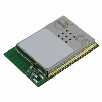
... MRF24WB0MA/MRF24WB0MB Pin Diagram Note: Antenna connector on MRF24WB0MB only. DS70632A-page 4 Preliminary 2010 Microchip Technology Inc. ...
Page 5
... When contacting a sales office, please specify which device, revision of silicon and data sheet (include literature number) you are using. Customer Notification System Register on our web site at www.microchip.com to receive the most current information on all of our products. 2010 Microchip Technology Inc. MRF24WB0MA/MRF24WB0MB Preliminary DS70632A-page 5 ...
Page 6
... MRF24WB0MA/MRF24WB0MB NOTES: DS70632A-page 6 Preliminary 2010 Microchip Technology Inc. ...
Page 7
... PCB Matching Antenna Circuitry (MRF24WB0MA ) 2010 Microchip Technology Inc. MRF24WB0MA/MRF24WB0MB The MRF24WB0MA/MRF24WB0MB modules have received regulatory approvals for modular devices in the United States (FCC), Canada (IC), and Europe (ETSI). The modular approval removes the need for expensive RF and antenna design, and allows the end ...
Page 8
... MRF24WB0MA/MRF24WB0MB FIGURE 1-2: MICROCONTROLLER TO MRF24WB0MA/MRF24WB0MB INTERFACE External Antenna (MRF24WB0MB) +3.3V (Typ) GND DS70632A-page 8 MRF24WB0Mx CS SDI SDO SCK INT VDD HIBERNATE GND WP RESET Preliminary PIC Microcontroller I/O SDO SDI SCK INTx I/O I/O I/O 2010 Microchip Technology Inc. ...
Page 9
... WP is used as write-protect for the internal module SPI Flash. For production use, this pin should be pulled low. For end application, this pin can be controlled by the host microcontroller to enable in field Flash updates. 2010 Microchip Technology Inc. MRF24WB0MA/MRF24WB0MB Description P Ground ...
Page 10
... The MRF24WB0MA/MRF24WB0MB is a surface mountable module. Module dimensions are shown in Figure 1-3. The module Printed Circuit Board (PCB thick with castellated mounting points on two sides. FIGURE 1-3: MRF24WB0MA/MRF24WB0MB MODULE PHYSICAL DIMENSIONS DS70632A-page 10 Note: Antenna connector on MRF24WB0MB only. Preliminary 2010 Microchip Technology Inc. ...
Page 11
... Figure 1-4. FIGURE 1-4: RECOMMENDED PCB FOOTPRINT Note 1: The “Note 1” demarcation specifies the “Host PCB copper keep-out area”. 2010 Microchip Technology Inc. MRF24WB0MA/MRF24WB0MB For best performance, mount the module on the edge of the host PCB with the antenna pattern facing outward ...
Page 12
... MODULE REFLOW PROFILE Zone 1 Temperature (°C) 180° Note 1: Conveyor Speed: 90 cm/min DS70632A-page 12 Zones 100 150 200 Time (Seconds) ( 180° 200° 200° 200° Preliminary 250 300 220° 265° 270° 2010 Microchip Technology Inc. ...
Page 13
CIRCUIT DESCRIPTION The MRF24WB0MA/MRF24WB0MB interfaces to Microchip PIC18, PIC24, dsPIC33, and PIC32 microprocessors with a minimal of external components through digital-only connections. This section details use of the module, starting with an example host connection as shown in Figure ...
Page 14
... ACTIVE STATE The Active state is identified as one of two states where the radio circuitry is fully on. There is the Receive state (RX ON) and the Transmit state (TX ON). Preliminary Time 2010 Microchip Technology Inc. ...
Page 15
... JTAG port provides the optional hardware JTAG Reset input, JTAG . JTAG_EN and JTAG RST driven high to enable JTAG mode. JTAG should not be enabled during normal functional operation. This func- tion affects power state current. 2010 Microchip Technology Inc. MRF24WB0MA/MRF24WB0MB CS Description 0V Power is completely disconnected 3.3V All internal power regulators are OFF – ...
Page 16
... These patterns allow the designer to understand the performance of the module with respect to the position of the receive/transmit antenna at the other end of the link. Figure 2-4, Figure 2-5 and Figure 2-6 show the simulated radiation patterns expected from the PCB antenna. Preliminary 2010 Microchip Technology Inc. ...
Page 17
... FIGURE 2-4: AZIMUTH RADIATION PATTERN, 2.44GHZ Horizontal Vertical 270° 2010 Microchip Technology Inc. MRF24WB0MA/MRF24WB0MB 0° -10 dB -15 dB -20 dB 180° 90° DS70632A-page 17 ...
Page 18
... MRF24WB0MA/MRF24WB0MB FIGURE 2-5: RADIATION PATTERN ON SIDE WITH PCB ANTENNA, 2.44GHZ Horizontal Vertical 270° DS70632A-page 18 0° -10 dB -15 dB -20 dB 180° Preliminary 2010 Microchip Technology Inc. 90° ...
Page 19
... FIGURE 2-6: RADIATION PATTERN ALONG PIN EDGE, 2.44GHZ Horizontal 270° 2010 Microchip Technology Inc. MRF24WB0MA/MRF24WB0MB 0° -10 dB -15 dB -20 dB 180° 90° Vertical DS70632A-page 19 ...
Page 20
... Dipole 2 2.0 Omni 9 2.0 Omni 9 2.0 Preliminary Connector Vendor IPEX Aristotle IPEX Aristotle IPEX Aristotle IPEX Aristotle IPEX Aristotle IPEX Aristotle IPEX Aristotle IPEX Saytec RF-IPEX Saytec IPEX Saytec RF-IPEX Saytec IPEX Saytec RF-IPEX Saytec 2010 Microchip Technology Inc. ...
Page 21
... Microchip Technology Inc. MRF24WB0MA/MRF24WB0MB A user’s manual for the product should include the following statement: module ...
Page 22
... If the device is too small to meet this condition, the information can be included in the user manual upon agreement with Industry Canada.” The label is shown in the following example: Contains IC: 8248A-G21ZEROG Preliminary 2010 Microchip Technology Inc. Radio Standards demonstrates labeling ...
Page 23
... Committee (ERC) Recommendation “70-03 E”, downloadable from the European Communications Office (ERO): http://www.ero.dk 2010 Microchip Technology Inc. MRF24WB0MA/MRF24WB0MB The end user is responsible for ensuring compliance with harmonized frequencies and labeling require- ments for each country in which the end device is marketed and sold. ...
Page 24
... Wi-Fi equipments, and their certifications are completed (WFA ID: WFA7150). The certification effort undertaken will save customers time and money. For modular policy, please refer to WFA Module Policy (Ver- sion 2.2; MARCH 2006).” DS70632A-page 24 and Preliminary 2010 Microchip Technology Inc. ...
Page 25
... The module is capable of this operation. 2: While 3.63V is the maximum operating voltage, the module will detect an overvoltage condition at 4.2V and disable the RF Transmit function in 0.5 ms. This certification behavior pertaining to disabling transmission in unforeseen overvoltage conditions. 2010 Microchip Technology Inc. MRF24WB0MA/MRF24WB0MB Min -0 ...
Page 26
... Typ 0.1 (1) 250 10 85 115 154 (1) Min Typ 2412 -91 - (1) Min Typ 2412 +10 0.5 1.0 -0.5 Preliminary 2010 Microchip Technology Inc. Max Units µA µ Max Units 2484 MHz dBm dBm dBm dBm Max Units 2484 MHz dBm dB dB 0.5 ...
Page 27
... SCK T CS High time CSD T CS Setup time CSS T CS Hold time CSH T SDI Setup time SU T SDI Hold time HD T SDO Valid time V 2010 Microchip Technology Inc. MRF24WB0MA/MRF24WB0MB LSb In High-Impedance Don’t Care Min Preliminary T CSD T CSH T DIS LSb Out ...
Page 28
... MRF24WB0MA/MRF24WB0MB NOTES: DS70632A-page 28 Preliminary 2010 Microchip Technology Inc. ...
Page 29
... APPENDIX A: REVISION HISTORY Revision A (April 2010) Initial release of this document. 2010 Microchip Technology Inc. MRF24WB0MA/MRF24WB0MB Preliminary DS70632A-page 29 ...
Page 30
... MRF24WB0MA/MRF24WB0MB NOTES: DS70632A-page 30 Preliminary 2010 Microchip Technology Inc. ...
Page 31
... To register, access the Microchip web site at http://www.microchip.com, click on Customer Change Notification and follow the registration instructions. 2010 Microchip Technology Inc. MRF24WB0MA/MRF24WB0MB CUSTOMER SUPPORT Users of Microchip products can receive assistance through several channels: • ...
Page 32
... What deletions from the document could be made without affecting the overall usefulness there any incorrect or misleading information (what and where)? 7. How would you improve this document? DS70632A-page 32 Total Pages Sent ________ FAX: (______) _________ - _________ N Literature Number: DS70632A Preliminary 2010 Microchip Technology Inc. ...
Page 33
... To order or obtain information, e.g., on pricing or delivery, refer to the factory or the listed sales office PART NO Device Module Module Type Device MR24WB0MA/MRF24WB0MB; V range 2.7V to 3.6V DD Temperature Range C = 0C to +70C 2010 Microchip Technology Inc. MRF24WB0MA/MRF24WB0MB T -X Examples: Tape and Temperature a) Reel Range b) (Commercial) Preliminary . MRF24WB0MA/RM = Commercial temp. tray MRF24WB0MB/RM = Commercial temp. tray DS70632A-page 33 ...
Page 34
... Taiwan - Kaohsiung Tel: 886-7-536-4818 Fax: 886-7-536-4803 Taiwan - Taipei Tel: 886-2-2500-6610 Fax: 886-2-2508-0102 Thailand - Bangkok Tel: 66-2-694-1351 Fax: 66-2-694-1350 Preliminary 2010 Microchip Technology Inc. EUROPE Austria - Wels Tel: 43-7242-2244-39 Fax: 43-7242-2244-393 Denmark - Copenhagen Tel: 45-4450-2828 Fax: 45-4485-2829 France - Paris Tel: 33-1-69-53-63-20 ...