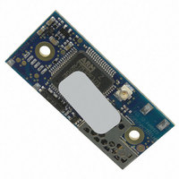
CB-OBS411X-04-0 ConnectBlue, CB-OBS411X-04-0 Datasheet - Page 37

CB-OBS411X-04-0
Manufacturer Part Number
CB-OBS411X-04-0
Description
BLUETOOTH V2.1+EDR MODULE 4DBM
Manufacturer
ConnectBlue
Specifications of CB-OBS411X-04-0
Frequency
2.4GHz
Data Rate - Maximum
115.2kbps
Modulation Or Protocol
Bluetooth v2.1+EDR, Class 2 & 3
Applications
General Purpose
Power - Output
4dBm
Sensitivity
-84dBm
Voltage - Supply
3 V ~ 6 V
Current - Receiving
15.5mA
Current - Transmitting
25.1mA
Data Interface
Solder Pads, 2 x 20mm, 1 mm pitch
Antenna Connector
U.FL
Operating Temperature
-30°C ~ 85°C
Package / Case
Module
Lead Free Status / RoHS Status
Lead free / RoHS Compliant
Memory Size
-
Other names
809-1034
connectBlue
Copyright © 2010 connectBlue AB
Figure 21: A red LED in a 5V host system. The status of the signal can also be used as input to a host controller.
The RED signal pin is also used to select Logic Level mode (instead of RS232) for connectBlue product with internal RS232 driver e.g.
cB-OEMSPA312. The mode functionality is not applicable on cB-OBS411 because there is no internal RS232 driver available. To be
compatible with these products check this signal in their Electrical and Mechanical datasheet.
The GREEN/Switch-1 signal is a multiplexed signal:
The signal is internally pulled-up (see
default values.
If a LED is used and a switch is required to be able to restore the settings, a high impendence buffer need to prevent the signal from
being pulled-up via the LED. See Figure 22-23 and the
Sometimes, over time, switch contacts can get an oxide layer. This may cause the closed switch resistance to become too high to sink
the signal to logic LOW because the signal is internally pulled-up (see
Figure 27.
Figure 22: Switch-1 used together with a green LED in a 3.3V host system. The status of the signal can also be used as input to
a host controller. Notice the 1kOhm serial resistor.
10.2.3.3 GREEN/Switch-1 signal
GREEN - Logic green LED signal (see the
time can be up to 2 seconds (see the Serial Port Adapter AT Commands specification).
Switch-1 - The module reads the status of the signal at startup to decide if the serial interface settings shall be restored (LOW).
The module will restore all factory settings if both the Switch-1 and Switch-0 signals are low during start up. See the Serial Port
Adapter AT Commands specification for more details. The input signal must be stable for the first 500ms after startup (after
reset/power on reset).
NOTE
The internal pull-up is changed compared to previous product generations from connectBlue. See the
Bluetooth cB-OEMSPA3xx to cB-OBS4xx products
Input/Output signals
Operating status
Logic Levels
) to the internal voltage supply (see
section for more information.
section). Becomes valid after the module has started up. The startup
section for buffer selection.
Input/Output signals
). A design that prevents this can be found in
Power supply
) for NOT restoring settings to
Migrating from
Page 37 of 42


