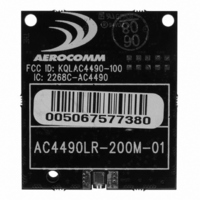
AC4490LR-200M Laird Technologies, AC4490LR-200M Datasheet - Page 17

AC4490LR-200M
Manufacturer Part Number
AC4490LR-200M
Description
TXRX 900MHZ 3.3-5.5V TTL 200MW
Manufacturer
Laird Technologies
Series
AeroCommr
Specifications of AC4490LR-200M
Frequency
902MHz ~ 928MHz
Data Rate - Maximum
115.2kbps
Modulation Or Protocol
FHSS, FSK
Applications
AMR, Fire & Security Alarms, Telemetry
Power - Output
5mW ~ 200mW
Sensitivity
-110dBm
Voltage - Supply
3.3V, 5V
Current - Transmitting
68mA
Data Interface
Connector, 2 x 10 Header
Antenna Connector
MMCX
Operating Temperature
-40°C ~ 85°C
Package / Case
Module
Output Power
200 mW
Lead Free Status / RoHS Status
Contains lead / RoHS non-compliant
Memory Size
-
Current - Receiving
-
Lead Free Status / Rohs Status
Lead free / RoHS Compliant
AC4490 User’s Manual
E n h a n c e d A P I R e c e i v e P a c k e t
Implemented in v6.7 of the firmware and later. By default, the source MAC is not included in the received data string
sent to the OEM Host. For applications where multiple radios are sending data, it may be necessary to determine the
origin of a specific data packet. When API Receive Packet is enabled, all packets received by the transceiver will
include the MAC address of the source radio as well as an RSSI indicator which can be used to determine the link
quality between the two.
API Receive Packet is enabled when bit-0 of the Enhanced API Control byte is enabled. Upon receiving a packet the
radio sends its OEM Host the packet in the following format:
Note: If Enhanced API Receive is enabled, the Receive API feature should be disabled by setting EEPROM byte 0xC1
to 0xFF.
P R O T O C O L S T A T U S / R E C E I V E A C K N O W L E D G E M E N T
Implemented in v6.3 of the firmware and later. When enabled in EEPROM, GO0 and GO1 will perform the functions of
Protocol Status and Receive Acknowledgement.
P r o t o c o l S t a t u s
Every time the radio hops to hop bin 0, the radios will assert GO0 Low for the entire hop bin. GO0 will go Low at the
falling edge of the Hop Frame at the start of bin 0 and will go High with the rising edge of Hop Frame at the end of bin
0. During all other hops, GO0 will be high. This mode is incompatible with modem mode.
R e c e i v e A c k n o w l e d g e m e n t
The radio uses GO1 to signal that a valid RF acknowledgement has been received from the remote radio. GO1 is
normally Low and will go High within approximately 75 us of receivinng a valid RF acknowledgement. It will remain
High until the end (rising edge) of the next hop. This mode is incompatible with Modem mode.
L O N G R A N G E M O D E
Specific to the AC4490LR-200 and AC4490LR-1000 transceivers, Long Range mode increases the receiver sensitivity
and range of the radio when enabled in EEPROM. Under some circumstances, such as in areas with extrememly high
interference levels, Long Range Mode may provide unsatisfactory results. In such cases, normal radio operation can
E N G I N E E R ’ S T I P
When both API Send Data Complete and API Receive Packet are enabled, the Send Data
Complete will be received before the transceiver sees the Receive API Packet. This order may
get reversed when the API Send Data Complete is missed and is being resent after the API
Receive Packet is received.
0x81
3
A success will always be displayed when sending broadcast packets after all broadcast attempts
have been exhausted.
Payload Data
(0x01 - 0x50)
Length
www.aerocomm.com
Aerocomm
Use
RSSI*
Source MAC
(2,1,0)
T H E O R Y O F O P E R A T I O N
Payload
Data
11


