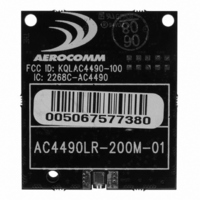
AC4490LR-200M Laird Technologies, AC4490LR-200M Datasheet - Page 22

AC4490LR-200M
Manufacturer Part Number
AC4490LR-200M
Description
TXRX 900MHZ 3.3-5.5V TTL 200MW
Manufacturer
Laird Technologies
Series
AeroCommr
Specifications of AC4490LR-200M
Frequency
902MHz ~ 928MHz
Data Rate - Maximum
115.2kbps
Modulation Or Protocol
FHSS, FSK
Applications
AMR, Fire & Security Alarms, Telemetry
Power - Output
5mW ~ 200mW
Sensitivity
-110dBm
Voltage - Supply
3.3V, 5V
Current - Transmitting
68mA
Data Interface
Connector, 2 x 10 Header
Antenna Connector
MMCX
Operating Temperature
-40°C ~ 85°C
Package / Case
Module
Output Power
200 mW
Lead Free Status / RoHS Status
Contains lead / RoHS non-compliant
Memory Size
-
Current - Receiving
-
Lead Free Status / Rohs Status
Lead free / RoHS Compliant
1 6
S E R I A L I N T E R F A C E
F L O W C O N T R O L
Flow control refers to the control of data flow between transceivers. It is the method used to handle data in the
transmit/receive buffer and determines how data flow between the transceivers is started and stopped. Often, one
transceiver is capable of sending data much faster than the other can receive and flow control allows the slower
device to tell the faster device when to pause and resume data transmission.
When a transceiver has data to send, it sends a Ready To Send signal and waits for a Clear To Send response from
the receiving unit. If the receiving radio is ready to accept data it will assert its CTS low. CTS will be reasserted when
the buffer contains the number of bytes specified by CTS_OFF (EEPROM address 0x5D). These signals are sent
apart from the data itself on separate wires.
H A L F D U P L E X / F U L L D U P L E X
When Half Duplex communication is chosen, the AC4490 will send a packet out over the RF whenever it can. This can
cause packets sent by multiple transceivers at the same time to collide with each other over the RF. To prevent this,
Full Duplex communication can be chosen. Full Duplex shares the bandwidth intelligently to enable two-way
collision-free communication without any collision. This is done by calculating the amount of time until the next hop to
ensure that it has time to send the packet; if there is enough time, it will send the packet and if not, it will wait until its
next appropriate hop. The Server transmits during the even hops while the Client(s) will transmit during the odd hops.
Although the RF hardware is still technically half duplex, the bandwidth sharing it makes the transceiver seem full
duplex. Enabling Full Duplex can cause overall throughputs to be cut in half.
S Y S T E M T I M I N G & L A T E N C Y
Care should be taken when selecting transceiver architecture, as it can have serious effects on data rates, latency,
and overall system throughput. The importance of these three characteristics will vary from system to system and
E N G I N E E R ’ S T I P
Can I implement a design using just Txd, Rxd and Gnd (Three-wire Interface)?
Yes. However, it is strongly recommended that your hardware monitor the CTS pin of the
radio. CTS is taken High by the radio when its interface buffer is getting full. Your hardware
should stop sending at this point to avoid a buffer overrun (and subsequent loss of data).
You can perform a successful design without monitoring CTS. However, you need to take into
account the amount of latency the radio adds to the system, any additional latency caused by
Transmit Retries or Broadcast Attempts, how often you send data, non-delivery network
timeouts and interface data rate. Polled type networks, where the Server host requests data
from the Client host and the Client host responds, are good candidates for avoiding the use of
CTS. This is because no one transceiver can monopolize the RF link. Asynchronous type
networks, where any radio can send to another radio at any point in time, are much more
difficult to implement without the use of CTS.


