PIXLITE-DIL-PLFE Flexipanel, PIXLITE-DIL-PLFE Datasheet - Page 6
PIXLITE-DIL-PLFE
Manufacturer Part Number
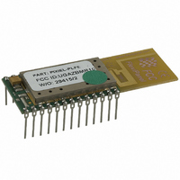
PIXLITE-DIL-PLFE
Description
MODULE ZIGBEE SW FAST 24-DIP
Manufacturer
Flexipanel
Series
Pixie™r
Specifications of PIXLITE-DIL-PLFE
Frequency
2.4GHz
Modulation Or Protocol
802.15.4 Zigbee
Power - Output
0dBm
Voltage - Supply
2.1 V ~ 3.6 V
Current - Receiving
25mA
Current - Transmitting
25mA
Data Interface
PCB, Through Hole
Memory Size
32kB ROM, 1536B RAM
Antenna Connector
On-Board, Trace
Operating Temperature
-40°C ~ 85°C
Package / Case
24-DIP Module
Lead Free Status / RoHS Status
Lead free / RoHS Compliant
Applications
-
Sensitivity
-
Data Rate - Maximum
-
Other names
658-1006-5
PIXIE-LITE-PLFE
PIXIE-LITE-PLFE


end devices are more likely to be RFDs and may be
battery powered.
Microchip Technology Inc provides a ZigBee stack,
complete
microcontrollers, including Pixies.
www.microchip.com to obtain the stack and for technical
support.
required include:
Refer to Microchip Technology’s documentation for full
details of the capabilities of the 18LF4520 and
18LF2520 microprocessors.
The Pixie Evaluation Kit contains two Pixie Evaluation
Boards
development work.
through the use of a packet sniffer such as Pixie Sniffer.
Sniffer software is freely available from FlexiPanel Ltd
for use with MACdongle, FlexiPanel’s USB Sniffer
device.
It is difficult to use breakpoints to debug ZigBee stack
code, since they halt the processing of the stack. The
UART provides an invaluable tool for debugging and
diagnostics.
RS232 level converters so that diagnostic messages
may be viewed in terminal emulators such as Microsoft
Windows HyperTerminal.
The Pixie Configuration Tool may be used to connect
the Pixie UART to a USB port. The Configuration Tool
generates 5V TTL serial data, so the level converter
shown in figure 7 should be used to interface to the
Pixie. This is provided in the Pixie Evaluation Boards
and may also be used to implement a very low cost
configuration and diagnostics port in commercial
products.
When working from demo code provided by Microchip
Technology, bear in mind the following:
p6
17-Mar-08
Pin 4 provides 5V up to 50mA and could power Pixie via a regulator
- MPLAB development environment
- IDC2 Programmer / Debugger
- C18 compiler
- Pixie Evaluation Boards
and
Typical Microchip development components
with
Figure 7. Config tool connector circuit
Pixie
The Pixie Evaluation Boards provide
may
source
TxD
RxD
Vss
Circuit diagnosis is much aided
be
Pixie DS481-17
code,
used
4k7
5V
for
for
(4-way 0.1 inch header)
Config tool connector
Please refer to
Pin 4 (Yellow)
Pin 3 (Blue)
Pin 2 (Red)
evaluation
Pin 1 (Black)
use
with
© FlexiPanel Ltd
PIC
and
PIC Programming
The PIC microcontroller may be programmed and/or
debugged with Microchip Technology’s ICD2 debugger
or PM3 programmer using the connections shown in
table 3.
An RJ11 connector is provided on the Pixie Evaluation
Boards for connection to the ICD2 programmer.
module should be independently powered at 3.3V
during programming.
If pins RE3 / RB6 / RB7 are used for purposes other
than programming / debugging, steps should be taken
to isolate them from the rest of the circuit during
programming/debugging. Refer to the ICSP application
notes in the bibliography.
Configuration Bits & Compile Options
Consider the following issues when setting compiler
options and configuration bits, etc:
Patents may apply and/or pending
Table 3. Programming connections
Pin
RE3
RB6
RB7
Gnd
Vdd
Pin RE3 may be configured to operate as a reset
pin or as a digital input, according to the
configuration bits. If configured as a reset pin,
appropriate reset circuitry should be provided by
the OEM.
The oscillator operates at 16MHz; the Microchip
demo code expects a 4MHz oscillator. To convert
to
configuration from “HS PLL” to “HS”.
examples, this is achieved by changing the line:
Operation at 16MHz is only guaranteed down to
2.7V.
reducing the clock speed to 4MHz. This may be
achieved by using the internal oscillator block at
4MHz. The CLOCK_FREQ definition in the ZigBee
stack should then be adjusted to 4000000.
The Microchip ZigBee Stack expects the following
C18 compiler settings: Small Code Model, Large
Data Model.
depend on requirements. Most likely, Pixie
running FFD firmware will require a multi-bank
stack, whereas Pixie Lite running RFD firmware
will only require a single-bank stack.
To fit an entire application and the ZigBee stack
onto the PICs provided, most object files will have
to be compiled with all optimizations enabled.
to:
rom unsigned char config1H = 0b00000110;
rom unsigned char config1H = 0b00000010;
16MHz,
For operation down to 2.1V, consider
Description
Vpp programming voltage
PGC programming clock
PGD programming data
Power ground reference
Power supply reference
simply
Single or Multi Bank Stack will
change
www.FlexiPanel.com
the
oscillator
In some
The
Related parts for PIXLITE-DIL-PLFE
Image
Part Number
Description
Manufacturer
Datasheet
Request
R

Part Number:
Description:
MODULE ZIGBEE SW FAST 24-SMD
Manufacturer:
Flexipanel
Datasheet:

Part Number:
Description:
MODULE ZIGBEE SW SLEEPY 24SMD
Manufacturer:
Flexipanel
Datasheet:

Part Number:
Description:
MODULE ZIGBEE SW SLEEPY 24DIP
Manufacturer:
Flexipanel
Datasheet:

Part Number:
Description:
IC USB ASYNC SRL UART 20-SSOP
Manufacturer:
Flexipanel
Datasheet:

Part Number:
Description:
IC USB SYNC SRL SPI 20-SSOP
Manufacturer:
Flexipanel
Datasheet:

Part Number:
Description:
IC USB SYNC SRL I2C 20-SSOP
Manufacturer:
Flexipanel
Datasheet:

Part Number:
Description:
IC USB ASYNC SRL UART 28-DIL
Manufacturer:
Flexipanel
Datasheet:

Part Number:
Description:
IC USB SYNC SRL I2C 28-DIL
Manufacturer:
Flexipanel
Datasheet:

Part Number:
Description:
IC USB SYNC SRL SPI 28-DIL
Manufacturer:
Flexipanel
Datasheet:

Part Number:
Description:
IC ENCRYPT KEY
Manufacturer:
Flexipanel
Datasheet:

Part Number:
Description:
IC ENCRYPT KEY 28-SSOP
Manufacturer:
Flexipanel
Datasheet:

Part Number:
Description:
IC ENCRYPT KEY 28-DIL
Manufacturer:
Flexipanel
Datasheet:

Part Number:
Description:
IC SYSTEM USB FAT FILE 20-SSOP
Manufacturer:
Flexipanel
Datasheet:

Part Number:
Description:
IC SYSTEM DATA LOGGER 20-SSOP
Manufacturer:
Flexipanel
Datasheet:

Part Number:
Description:
IC CTRLR TOUCH KEYED 20-SSOP
Manufacturer:
Flexipanel
Datasheet: