PIXLITE-DIL-PLFE Flexipanel, PIXLITE-DIL-PLFE Datasheet - Page 9
PIXLITE-DIL-PLFE
Manufacturer Part Number
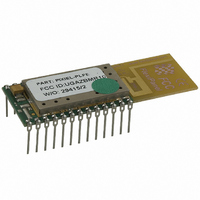
PIXLITE-DIL-PLFE
Description
MODULE ZIGBEE SW FAST 24-DIP
Manufacturer
Flexipanel
Series
Pixie™r
Specifications of PIXLITE-DIL-PLFE
Frequency
2.4GHz
Modulation Or Protocol
802.15.4 Zigbee
Power - Output
0dBm
Voltage - Supply
2.1 V ~ 3.6 V
Current - Receiving
25mA
Current - Transmitting
25mA
Data Interface
PCB, Through Hole
Memory Size
32kB ROM, 1536B RAM
Antenna Connector
On-Board, Trace
Operating Temperature
-40°C ~ 85°C
Package / Case
24-DIP Module
Lead Free Status / RoHS Status
Lead free / RoHS Compliant
Applications
-
Sensitivity
-
Data Rate - Maximum
-
Other names
658-1006-5
PIXIE-LITE-PLFE
PIXIE-LITE-PLFE


If soldering manually, use the following procedure:
Location on main board
The module should be located so that the antenna abuts
the edge of the board or overhangs it. It should be
placed so that it is unlikely that interfering items such as
metal, water, cellphones, body tissue, etc, can come
into close proximity.
It is recommended that tracks and components are not
placed in PCB layers below the module. However, if
space limitations require it, leave the surface in contact
with the module uncoppered and place a grounded fill in
the layer immediately below. Any vias that might come
in contact with the module should be completely
covered with resist to avoid shorting to vias on the
module.
grounded copper fill as possible in order to reduce
circuit noise.
Enclosures
Metal enclosures are not recommended for attenuation
reasons. If one must be used, aim to put as many holes
in it as possible at least 3cm long.
For mains isolation and intrinsic safety applications,
potting in a shallow layer of clear potting compound is
recommended. A 5mm layer of potting compound (RS
Components p/n 199-1468) has been measured to
attenuate the signal by approximately 3dB. LEDs can
be clearly seen through the potting compound and bind
switches, etc, can be implemented using reed switches.
For all-weather and external mounting applications,
contact us for a range of puck antenna enclosures.
p9
1. Tin the contact pads on the module, trying to get
2. Tin contact pads on main board.
3. Place the module in position on the main board.
4. Starting with the pads most likely to be in physical
5. Test for continuity between the pad on the upper
6. Rework non-conducting contacts by applying heat
more or less the same amount of solder on each.
Work on a soft surface so that the components on
the topside are not damaged.
contact, apply heat with a soldering iron to the
exposed part of the main board pads. Abut the iron
against the edge of the module so that the heat is
transmitted to the contact area of the pads. After
10-15 seconds, remove heat. Around 90% of pads
should be successfully soldered.
side of the board and the protruding part of the pad
on the main board.
again and a little extra solder.
17-Mar-08
The main board should contain as much
Pixie DS481-17
© FlexiPanel Ltd
Pixie Lite
Pixie Lite is a reduced function device based on the
18LF2520 microprocessor. It has sufficient memory to
implement end devices only.
Bear the following points in mind when developing
applications with Pixie Lite:
See Appendix I for a suitable linker script for the
Microchip
PIC18LF2520.
Future releases of Pixie & Pixie Lite
The following changes are anticipated in future revisions
of Pixie and Pixie Lite.
Bibliography
ZigBee for Applications Developers, white paper
downloadable from www.flexipanel.com.
ZigBee Specification, downloadable from
www.zigbee.org.
EasyBee Data Sheet, downloadable from
www.flexipanel.com.
PICDEM Z User Guide, downloadable from
www.microchip.com.
AN965 Microchip Stack for the ZigBee Protocol,
application note, downloadable from
www.microchip.com.
Microchip Stack for ZigBee Protocol, supplementary
notes included with the Microchip Stack for ZigBee
firmware downloadable from www.microchip.com.
PIC18F4620 Data Sheet, downloadable from
www.microchip.com.
Patents may apply and/or pending
Pin connections RE1 and RE2 are not present
and their pads should be omitted on the PCB
layout.
The firmware must be recompiled to suit an
18LF2520 target.
Flash table writes are 32 bytes instead of 64 so
the
set to
A single-bank stack model is recommended.
ROM reduces from 64K to 32K.
RAM reduces from 3986 bytes to 1536.
The 18LF2520 on the Pixie Lite may be replaced
by an 18LF2620 if new features in the ZigBee
stack, such as security, require the extra memory.
WRITE_BLOCK_SIZE
32ul
Stack
. (See Microchip DS80229B.)
for
ZigBee
value in
running
www.FlexiPanel.com
zNVM.c
on
must be
the
Related parts for PIXLITE-DIL-PLFE
Image
Part Number
Description
Manufacturer
Datasheet
Request
R

Part Number:
Description:
MODULE ZIGBEE SW FAST 24-SMD
Manufacturer:
Flexipanel
Datasheet:

Part Number:
Description:
MODULE ZIGBEE SW SLEEPY 24SMD
Manufacturer:
Flexipanel
Datasheet:

Part Number:
Description:
MODULE ZIGBEE SW SLEEPY 24DIP
Manufacturer:
Flexipanel
Datasheet:

Part Number:
Description:
IC USB ASYNC SRL UART 20-SSOP
Manufacturer:
Flexipanel
Datasheet:

Part Number:
Description:
IC USB SYNC SRL SPI 20-SSOP
Manufacturer:
Flexipanel
Datasheet:

Part Number:
Description:
IC USB SYNC SRL I2C 20-SSOP
Manufacturer:
Flexipanel
Datasheet:

Part Number:
Description:
IC USB ASYNC SRL UART 28-DIL
Manufacturer:
Flexipanel
Datasheet:

Part Number:
Description:
IC USB SYNC SRL I2C 28-DIL
Manufacturer:
Flexipanel
Datasheet:

Part Number:
Description:
IC USB SYNC SRL SPI 28-DIL
Manufacturer:
Flexipanel
Datasheet:

Part Number:
Description:
IC ENCRYPT KEY
Manufacturer:
Flexipanel
Datasheet:

Part Number:
Description:
IC ENCRYPT KEY 28-SSOP
Manufacturer:
Flexipanel
Datasheet:

Part Number:
Description:
IC ENCRYPT KEY 28-DIL
Manufacturer:
Flexipanel
Datasheet:

Part Number:
Description:
IC SYSTEM USB FAT FILE 20-SSOP
Manufacturer:
Flexipanel
Datasheet:

Part Number:
Description:
IC SYSTEM DATA LOGGER 20-SSOP
Manufacturer:
Flexipanel
Datasheet:

Part Number:
Description:
IC CTRLR TOUCH KEYED 20-SSOP
Manufacturer:
Flexipanel
Datasheet: