STEVAL-TDR013V1 STMicroelectronics, STEVAL-TDR013V1 Datasheet
STEVAL-TDR013V1
Specifications of STEVAL-TDR013V1


Related parts for STEVAL-TDR013V1


STEVAL-TDR013V1 Summary of contents
Page 1
Features ■ Excellent thermal stability ■ Common source configuration ■ Broadband performances P dB gain @ 870 MHz ■ Plastic package ■ ESD protection ■ Supplied in tape and reel ■ In compliance with the 2002/95/EC european directive Description The ...
Page 2
Contents Contents 1 Electrical data . . . . . . . . . . . . . . . . . . . . . . . . . . . . . . . . . . . ...
Page 3
PD84002 1 Electrical data 1.1 Maximum ratings Table 1. Absolute maximum ratings (T Symbol V (BR)DSS DISS STG 1.2 Thermal data Table 2. Thermal data Symbol R thJC CASE Parameter Drain-source voltage ...
Page 4
Electrical characteristics 2 Electrical characteristics T = +25 CASE 2.1 Static Table 3. Static Symbol DSS GSS 7.5 V GS( ...
Page 5
PD84002 3 Impedances Figure 3. Impedances Table 7. Impedances F(MHz) 860 870 880 890 900 910 920 930 940 7,79 1, 7,96 1, 8,01 1, 8,11 1, ...
Page 6
DC curves 4 DC curves Figure 4. DC output characteristics Figure 6. Capacitances vs drain voltage 6/16 Figure 5. VGS=10V VGS=9V VGS=8V VGS=7V VGS=6V VGS=5V VGS=4V CRSS COSS CISS 6 ...
Page 7
PD84002 5 RF curves Figure 7. Output power and efficiency vs frequency 7 100 mA / Pin = 19 dBm Pout Eff 0 820 840 860 880 900 920 Freq (MHz) Figure 9. ...
Page 8
Schematic and BOM 6 Schematic and BOM Figure 12. Schematic MSub FR4 H=20 mil RFin C4 C6 Table 8. Components part list Component ID Description B1 Ferrite Bead B2 Ferrite Bead C1, C2 Capacitor C3 Capacitor C4, C5 Capacitor C6, ...
Page 9
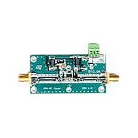
... RF in, RF out SMA-CONN PD84002 LDMOS Board 7 Photo Figure 13. Photo Value Case size Manufacturer W=0.92 mm L=13.6 mm W=0.92 mm L=3.5 mm W=0.92 mm L=4.2 mm W=0.92 mm L=3.8 mm W=0.92 mm L=3.7 mm W=0.92 mm L=11 Ω 60 mils STMicroelectronics FR-4 THk=0.020" 2OZ Cu Both Sides Part Code JOHNSON 142-0701-801 PD84002 Photo 9/16 ...
Page 10
Package mechanical data 8 Package mechanical data In order to meet environmental requirements, ST offers these devices in ECOPACK® packages. These packages have a Lead-free second level interconnect . The category of second level interconnect is marked on the package ...
Page 11
PD84002 Table 9. SOT-89 mechanical data Dim Figure 14. Package dimensions mm. Min Typ Max 1.4 1.6 0.44 0.56 0.36 0.48 0.35 0.44 0.35 0.44 4.4 4.6 1.62 ...
Page 12
Package mechanical data 8.1 Thermal pad and via design Thernal vias are required in the PCB layout to effectively conduct heat away from the package. The via pattern has been designed to address thermal, power dissipation and electrical requirements of ...
Page 13
PD84002 8.2 Soldering profile Figure 16 shows the recommeded solder for devices that have Pb-free terminal plating and where a Pb-free solder is used. Figure 16. Recommended solder profile Figure 17 shows the recommeded solder for devices with Pb-free terminal ...
Page 14
Package mechanical data Figure 18. Reel information 14/16 PD84002 ...
Page 15
PD84002 9 Revision history Table 10. Document revision history Date 05-Dec-2007 Revision 1 Initial release. Revision history Changes 15/16 ...
Page 16
... Information in this document is provided solely in connection with ST products. STMicroelectronics NV and its subsidiaries (“ST”) reserve the right to make changes, corrections, modifications or improvements, to this document, and the products and services described herein at any time, without notice. All ST products are sold pursuant to ST’s terms and conditions of sale. ...