GP1A17 Sharp Microelectronics, GP1A17 Datasheet

PHOTOINTER OPIC SLOT 10MM PCB

GP1A17

Manufacturer Part Number
GP1A17
Description
PHOTOINTER OPIC SLOT 10MM PCB
Manufacturer
Sharp Microelectronics
Series
OPIC™r
Datasheet

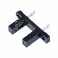
Specifications of GP1A17

Rohs Status
RoHS non-compliant
Sensing Distance
0.394" (10mm)
Sensing Method
Transmissive
Output Configuration
NPN - Open Collector
Mounting Type
Through Hole
Current - Supply
2.5mA
Voltage - Supply
4.5 V ~ 17 V
Response Time
0.1µs, 0.05µs
Package / Case
PCB Mount
Other names
425-1070-5

Available stocks

Company
Part Number
Manufacturer
Quantity
Price
Part Number:
GP1A17
Manufacturer:
SHARP
Quantity:
1 433
Part Number:
GP1A173
Manufacturer:
TOSHIBA
Quantity:
8 430
GP1A17
1. Built-in Schmidt trigger circuit
2. Wide gap between light emitter and detec-
3. Operating supply voltage V
4. TTL and CMOS compatible output
1. Copiers
2. Analyzers, measuring instruments, etc.
*1 Pules width
*2 For 5 seconds
data books, etc. Contact SHARP in order to obtain the latest version of the device specification sheets before using any SHARP's device. ”
“ In the absence of confirmation by device specification sheets, SHARP takes no responsibility for any defects that occur in equipment using any of SHARP's devices, shown in catalogs,
*2
Applications
Operating tamperature
Storage temperture
Soldering temperature
Features
Absolute Maximum Ratings
Output
Input
tor ( 10mm )
<=
100
*1
Forward current
Peak forward current
Reverse voltage
Power dissipation
Supply voltage
Output current
Power dissipation
s, Duty ratio = 0.01
Parameter
CC
: 4.5 to 17V
Symbol
V
T
T
T
I
V
P
I
I
P
FM
opr
stg
sol
F
CC
O
R
O
Wide Gap Type, OPIC Photointerrupter
5 -
*“ OPIC ” ( Optical IC ) is a trademark of the SHARP Corporation.
- 40 to + 100
An OPIC consists of a light-detecting element and signal-
processing circuit integrated onto a single chip.
- 0.5 to + 17
Outline Dimensions
- 25 to + 85
Internal connection diagram
Rating
0.45
1
2
250
260
50
75
50
1
6
± 0.2
2 -
2
1
( Ta = 25˚C )
25.4
32.0
( 15.24 )
3.2
18.6
10.0
± 0.2
± 0.3
± 0.2
Unit
mW
mW
mA
mA
4
˚C
˚C
˚C
A
V
V
5
4
3
3
5
( 10k )
Amp.
( 1.5 )
Voltage regulator
* Unspecified tolerances shall be
* ( ) : Reference dimensions
18.0< d<=25.0
2
as follows ;
Dimensions
6.0< d<=18.0
-
1 Anode
2 Cathode
C2.0
d<=6.0
( 1.27 )
6.0
( Unit : mm )
Tolerance
± 0.2
± 0.25
( 1.27 )
± 0.1
± 0.2
2.0
Slit width
( Both sides
GP1A17
of detector
and emitter )
3 V
4 V
5 GND
CC
O

Related parts for GP1A17

GP1A17 Summary of contents

Page 1

... 0 250 ˚C opr - 100 T ˚C stg T 260 ˚C sol GP1A17 ( Unit : Anode Cathode GND 2 C2.0 - ± 0.2 6.0 2.0 Slit width ( Both sides of detector and emitter ) ( 1. 1. Unspecified tolerances shall be as follows ; Dimensions Tolerance d<=6.0 ± 0.1 6.0< d<=18.0 ± ...

Page 2

... Fig. 2 Output Power Dissipation vs 100 MIN. TYP 7mA 4 2.5 = 7mA - 1.0 - 3.0 0.55 0. 0.1 - 0.05 Unit mA mA Ambient Temperature 300 250 200 150 100 Ambient temperature Ta ( ˚C ) GP1A17 ( Ta = 25˚C ) MAX. Unit 1 0 5.0 mA 3.0 mA 7 0.5 0 100 ...

Page 3

... V ) Forward voltage V F Ambient Temperature 1 1.2 I FLH 1.0 I FHL 0.8 0 Ta= 25˚C FLH 0 ˚C ) Ambient temperature T a Ambient Temperature 0 0 30mA OL 0.2 16mA 0.1 5mA ˚C ) Ambient temperature T a GP1A17 3 3.5 100 100 ...

Page 4

... As for other general cautions, refer to the chapter “Precautions for Use” . Fig.10 Propagation Delay Time vs 25˚C a 25˚C 85˚ 7mA 25˚ Input 280 10k V O 0.01 F Output Forward Current 280 25˚ Forward current PLH PHL V OH 90% 1.5V 10 GP1A17 t PHL t PLH 50 ...

Page 5

Application Circuits NOTICE The circuit application examples in this publication are provided to explain representative applications of SHARP devices and are not intended to guarantee any circuit design or license any intellectual property rights. SHARP takes no responsibility for any ...

Related keywords