GP1A35RV Sharp Microelectronics, GP1A35RV Datasheet

PHOTOINTERRUPTER OPIC SLOT 3.4MM

GP1A35RV

Manufacturer Part Number
GP1A35RV
Description
PHOTOINTERRUPTER OPIC SLOT 3.4MM
Manufacturer
Sharp Microelectronics
Series
OPIC™r
Datasheet

Specifications of GP1A35RV

Sensing Distance
0.134" (3.4mm)
Sensing Method
Transmissive
Output Configuration
NPN - Open Collector
Mounting Type
Through Hole
Voltage - Supply
5V
Response Time
1µs, 1µs
Package / Case
PCB Mount
Lead Free Status / RoHS Status
Contains lead / RoHS non-compliant
Current - Supply
-
Other names
425-1064
GP1A35RV
1. 2-phase ( A, B ) digital output
2. High sensing accuracy
3. TTL compatible output
4. Compact and light
1. Copiers
2. Electronic typewriters, printers
3. Numerical control machines
*1 Pulse width<=100 s, Duty ratio= 0.01
*2
( Disk slit pitch: 0.22mm, Moire stripe appli-
Operating temperature
Storage temperature
Applications
Absolute Maximum Ratings
Soldering temperature
Features
Output
cation )
Input
“ In the absence of confirmation by device specification sheets, SHARP takes no responsibility for any defects that occur in equipment using any of SHARP's devices, shown in catalogs,
data books, etc. Contact SHARP in order to obtain the latest version of the device specification sheets before using any SHARP's device.”
*1
Forward current
Reverse voltage
Power dissipation
Supply voltage
Low level output current
Power dissipation
Peak forward current
Parameter
*2 For 5 seconds
Symbol
V
T
T
T
I
V
I
P
I
P
FM
OL
opr
stg
sol
F
CC
R
O
High Sensing Accuracy OPIC
Photointerrupter with
Encoder Functions
*“ OPIC” ( Optical IC ) is a trademark of the SHARP Corporation.
An OPIC consists of a light-detecting element and signal-
Outline Dimensions
processing circuit integrated onto a single chip.
0.8
- 40 to + 80
3.9
0 to + 70
2
1
± 0.15
Rating
+ 0.1
( 7.08 )
100
250
260
- 0.2
65
20
1
6
7
7.3
12.0
2.0
+ 0.15
- 0.1
( Ta= 25˚C )
3
5
± 0.15
( 1.27 )
6
4
Unit
mW
mW
mA
mA
˚C
˚C
˚C
A
V
V
4 - R2.6
Internal connection diagram
*Tolerance:±
* ( ) : Reference dimensions
1 Anode
2 Cathode
3 V
1
2
2.0
OA
15.0
20.2
8.8
± 0.15
0.3mm
4 V
5 GND
6 V
( Unit : mm )
GP1A35RV
4.0
6
5
4
3
CC
OB
4 - R1.4
OPIC
± 0.15

Related parts for GP1A35RV

GP1A35RV Summary of contents

Page 1

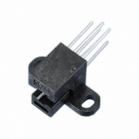
... Ta= 25˚C ) Symbol Rating 100 250 opr stg T 260 sol *2 For 5 seconds GP1A35RV ( Unit : mm ) Internal connection diagram OPIC 1 Anode Cathode 5 GND R2.6 8.8 4.0 2.0 ± 0. R1.4 ± 0.15 15.0 20.2 4 *Tolerance:± 0.3mm * ( ) : Reference dimensions Unit mA ...

Page 2

... Measured under the condition shown in Measurement Conditions. Fig. 2 Output Power Dissipation vs 100 ( ˚ MIN. TYP 30mA 2.4 4 30mA 0 30mA 2.4 4 30mA 0 30mA 1 1 100 Ambient Temperature 300 250 200 150 100 ˚C ) Ambient temperature T a GP1A35RV ( Ta= 25˚C ) MAX. Unit 130 deg. 2.0 s 2.0 100 ...

Page 3

... AB1 = x 360˚ AB1 ˚C ) Ambient temperature T a Distance ( Xdirection ) 140 30mA F 130 f= 12kHz T = 25˚C a 120 110 t AB1 = x 360˚ AB1 t AP 100 Reference position ( - ) ( + ) 90 GP1A35RV 1.0 - 0.5 0 0.5 Distance Shifting encoder ) GP1A35RV 100 Disk 1.0 ...

Page 4

... Disk 50 - 1.0 - 0.5 0 0.5 Distance Shifting encoder ) Distance ( Zdirection ) 30mA F f= 12kHz T = 25˚ AB1 =x 360 ˚ AB1 Detecting side ) Z 80 OPIC 70 ( Emitting side ) 60 0 0.1 0.2 0.3 0.4 0.5 0.6 0.7 0.8 Distance Shifting encoder ) GP1A35RV = 5V 1.0 Disk 0.9 1.0 ...

Page 5

... GP1A35RV R C 0.9 ˚ ( Number of slit 400 ) : 0.45 ˚ 4-R1.4 1A35R 1.4 6 Note 2 ) 9.9 12.86 = 30mA TYP GP1A35RV Detection signal of rotational direction 3 C • • C • W When gate delay causes pulse noise in Q4 output, apply the CR filter to remove pulse noise. ...

Page 6

Application Circuits NOTICE The circuit application examples in this publication are provided to explain representative applications of SHARP devices and are not intended to guarantee any circuit design or license any intellectual property rights. SHARP takes no responsibility for any ...

Related keywords