A16-1P Omron, A16-1P Datasheet - Page 22
A16-1P
Manufacturer Part Number
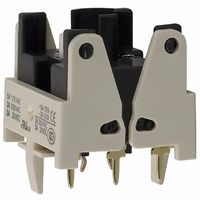
A16-1P
Description
SWTCH BLOCK SPDT PCB TERMINAL
Manufacturer
Omron
Type
Pushbuttonr
Datasheet
1.A16-5DSG.pdf
(28 pages)
Specifications of A16-1P
Accessory Type
Switch Block Replacement
Mounting Style
PCB
Termination Style
Solder
For Use With/related Products
A16 Series
For Use With
Z1398 - SWTCH KNOB RND 3POS DPDT ILL YLWZ1397 - SWTCH KNOB RND 3POS DPDT ILL REDZ1396 - SWTCH KNOB RND 3POS DPDT ILL GRNZ1395 - SWTCH KNOB RND 2POS SPDT ILL YLWZ1394 - SWTCH KNOB RND 2POS SPDT ILL REDZ1393 - SWTCH KNOB RND 2POS SPDT ILL GRNZ1392 - SWTCH KNOB RND 2POS SPDT ILL YLWZ1391 - SWTCH KNOB RND 2POS SPDT ILL REDZ1390 - SWTCH KNOB RND 2POS SPDT ILL GRNZ1389 - SWITCH KNOB RND 3-POS DPDTZ1388 - SWITCH KNOB RND 2-POS SPDTZ1387 - SWITCH KNOB RND 2-POS SPDTZ1386 - SWITCH KNB RECT 3POS DPDT ILLZ1385 - SWITCH KNB RECT 3POS DPDT ILLZ1384 - SWITCH KNB RECT 3POS DPDT ILLZ1383 - SWITCH KNB RECT 2POS SPDT ILLZ1382 - SWITCH KNB RECT 2POS SPDT ILLZ1381 - SWITCH KNB RECT 2POS SPDT ILLZ1380 - SWITCH KNB RECT 2POS SPDT ILLZ1379 - SWITCH KNB RECT 2POS SPDT ILLZ1378 - SWITCH KNB RECT 2POS SPDT ILLZ1377 - SWITCH KNOB RECT 3-POS DPDTZ1376 - SWITCH KNOB RECT 2-POS SPDTZ1375 - SWITCH KNOB RECT 2-POS SPDTZ1374 - SWITCH KNOB SQ 3-POS DPDT ILLZ1373 - SWITCH KNOB SQ 3-POS DPDT ILLZ1372 - SWITCH KNOB SQ 3-POS DPDT ILLZ1371 - SWITCH KNOB SQ 2-POS SPDT ILLZ1370 - SWITCH KNOB SQ 2-POS SPDT ILLZ1369 - SWITCH KNOB SQ 2-POS SPDT ILLZ1368 - SWITCH KNOB SQ 2-POS SPDT ILLZ1367 - SWITCH KNOB SQ 2-POS SPDT ILLZ1366 - SWITCH KNOB SQ 2-POS SPDT ILLZ1365 - SWITCH KNOB SQ 3-POS DPDTZ1364 - SWITCH KNOB SQ 2-POS SPDTZ1363 - SWITCH KNOB SQ 2-POS SPDTZ1328 - SWITCH PB ROUND MOM SPDT YELLOWZ1327 - SWITCH PB ROUND MOM SPDT WHITEZ1326 - SWITCH PB ROUND MOM SPDT REDZ1325 - SWITCH PB ROUND MOM SPDT GREENZ1324 - SWITCH PB ROUND MOM SPDT BLACKZ1323 - SWITCH PB ROUND MOM SPDT BLUEZ1322 - SWITCH PB RECT MOM DPDT YELLOWZ1321 - SWITCH PB RECT MOM DPDT WHITEZ1320 - SWITCH PB RECT MOM DPDT REDZ1319 - SWITCH PB RECT MOM DPDT GREENZ1318 - SWITCH PB RECT MOM DPDT BLACKZ1317 - SWITCH PB SQUARE MOM DPDT YELLOWZ1316 - SWITCH PB SQUARE MOM DPDT WHITEZ1315 - SWITCH PB SQUARE MOM DPDT REDZ1314 - SWITCH PB SQUARE MOM DPDT GREENZ1313 - SWITCH PB SQUARE MOM DPDT BLACKZ1312 - SWITCH PB SQUARE MOM DPDT BLUEZ1311 - SWITCH PB RND MOM DPDT ILLUM YLWZ1310 - SWITCH PB RND MOM DPDT ILLUM WHTZ1309 - SWITCH PB RND MOM DPDT ILLUM REDZ1308 - SWITCH PB RND MOM DPDT ILLUM GRNZ1307 - SWITCH PB RECT MOM DPDT ILLUMZ1306 - SWITCH PB RECT MOM DPDT ILLUMZ1305 - SWITCH PB RECT MOM DPDT ILLUMZ1304 - SWITCH PB RECT MOM DPDT ILLUMZ1303 - SWITCH PB SQ MOM DPDT ILLUM YLLWZ1302 - SWITCH PB SQ MOM DPDT ILLUM WHTZ1301 - SWITCH PB SQ MOM DPDT ILLUM REDZ1300 - SWITCH PB SQ MOM DPDT ILLUM GRN
Lead Free Status / RoHS Status
Lead free / RoHS Compliant
Lead Free Status / RoHS Status
Lead free / RoHS Compliant, Lead free / RoHS Compliant
Other names
A161P
Z1332
Z1332


Dimensions
PCB Terminals (Lamp terminals are also present on non-lighted models.)
Terminal Arrangement
Voltage-reduction Lighting (Lamp terminals are also present on non-lighted models.)
Solder Terminals
• The voltage-reduction circuit is built in.
Note: Secure the panel to the board using stud bolts
A = 24 min.: Rectangular
A = 21 min.: Square or round
L = 24 min.
Use a PCB with a thickness of 1.6 mm.
(Bottom View)
PCB Cutouts
Dimensions of
PCB Terminals
2.7
if force will be applied to the board after wiring.
Lamp terminal (t=0.5)
0.8
1.5
DPDT lighted models
(Bottom view)
3.5
20 ± 0.1 4.85 ± 0.05
5.3
12.4 ± 0.05
Side with TOP indicated
Side with direction arrow
Five, 1 dia.
Model, rating, and lot
number indication
Lighted SPDT Switches
6.3 ± 0.05
NC
NO
C
L
L
4.85
12.4
18.6
NC
NO
C
Two, 5 dia.
Side with TOP indicated
A ± 0.1
Terminal Arrangement
(Bottom View)
Screw-Less Clamps
Red (Release button)
White (Release button)
Black (Release button)
Black (Release button)
• Voltage-reduction lighting models with Screw-Less Clamps (A16L-@T1-2S, A16L-@T2-2S)
incorporate voltage-reduction circuits.
COM
SW 1
NC
NO
L-
L ± 0.1
A = 24 min.: Rectangular
A = 21 min.: Square or round
L = 24 min.
Use a PCB with a thickness of 1.6 mm.
Note: Secure the panel to the board using stud bolts
Dimensions of
PCB Terminals
(Bottom View)
PCB Cutouts
Lamp terminal (t=0.5)
2.7
if force will be applied to the board after wiring.
0.8
1.5
3.5
20 ± 0.1
5.3
DPDT lighted models
Red (Release button)
12.4 ± 0.05
Black (Release button)
Side with TOP indicated
4.85 ± 0.05
Lighted DPDT Switches
12-3.1 dia. (Insertion hole)
Red (Release button)
White (Release button)
Black (Release button)
Black (Release button)
6.3 ± 0.05
4.85
12.4
18.6
Two, 5 dia.
Terminal Arrangement
Side with TOP indicated
(Bottom View)
6.3 ± 0.05
A ± 0.1
SW 1
COM
Side indicating TOP
NC
NO
NC2
NO2
C2
C2
L-
SW 2
COM
NC
NO
(Unit: mm)
-
+
+
A16
NC1
NO1
C1
C1
L ± 0.1
Eight, 1 d
22
Related parts for A16-1P
Image
Part Number
Description
Manufacturer
Datasheet
Request
R

Part Number:
Description:
SWITCH PB SQUARE MOM SPDT GREEN
Manufacturer:
Omron
Datasheet:

Part Number:
Description:
SWITCH PB SQUARE MOM SPDT WHITE
Manufacturer:
Omron
Datasheet:
Part Number:
Description:
SWITCH PB SQUARE MOM SPDT YELLOW
Manufacturer:
Omron
Datasheet:
Part Number:
Description:
SWITCH PB RECTANG MOM SPDT BLUE
Manufacturer:
Omron
Datasheet:
Part Number:
Description:
SWITCH PB RECTANG MOM SPDT YEL
Manufacturer:
Omron
Datasheet:
Part Number:
Description:
SWITCH PB SQUARE MOM SPDT BLUE
Manufacturer:
Omron
Datasheet:
Part Number:
Description:
SWITCH PB SQUARE MOM SPDT RED
Manufacturer:
Omron
Datasheet:
Part Number:
Description:
SWITCH PB RECTANG MOM SPDT GREEN
Manufacturer:
Omron
Datasheet:
Part Number:
Description:
SWITCH PB RECTANG MOM SPDT RED
Manufacturer:
Omron
Datasheet:

Part Number:
Description:
SWITCH PB RECTANG MOM SPDT WHITE
Manufacturer:
Omron
Datasheet:
Part Number:
Description:
SWITCH PB ROUND MOM SPDT BLUE
Manufacturer:
Omron
Datasheet:
Part Number:
Description:
SWITCH PB ROUND MOM SPDT GREEN
Manufacturer:
Omron
Datasheet:
Part Number:
Description:
SWITCH PB ROUND MOM SPDT RED
Manufacturer:
Omron
Datasheet:
Part Number:
Description:
SWITCH PB ROUND MOM SPDT WHITE
Manufacturer:
Omron
Datasheet:
Part Number:
Description:
SWITCH PB ROUND MOM SPDT YELLOW
Manufacturer:
Omron
Datasheet: