A16-1P Omron, A16-1P Datasheet - Page 25
A16-1P
Manufacturer Part Number
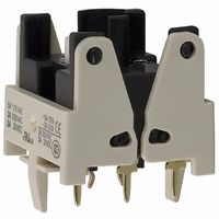
A16-1P
Description
SWTCH BLOCK SPDT PCB TERMINAL
Manufacturer
Omron
Type
Pushbuttonr
Datasheet
1.A16-5DSG.pdf
(28 pages)
Specifications of A16-1P
Accessory Type
Switch Block Replacement
Mounting Style
PCB
Termination Style
Solder
For Use With/related Products
A16 Series
For Use With
Z1398 - SWTCH KNOB RND 3POS DPDT ILL YLWZ1397 - SWTCH KNOB RND 3POS DPDT ILL REDZ1396 - SWTCH KNOB RND 3POS DPDT ILL GRNZ1395 - SWTCH KNOB RND 2POS SPDT ILL YLWZ1394 - SWTCH KNOB RND 2POS SPDT ILL REDZ1393 - SWTCH KNOB RND 2POS SPDT ILL GRNZ1392 - SWTCH KNOB RND 2POS SPDT ILL YLWZ1391 - SWTCH KNOB RND 2POS SPDT ILL REDZ1390 - SWTCH KNOB RND 2POS SPDT ILL GRNZ1389 - SWITCH KNOB RND 3-POS DPDTZ1388 - SWITCH KNOB RND 2-POS SPDTZ1387 - SWITCH KNOB RND 2-POS SPDTZ1386 - SWITCH KNB RECT 3POS DPDT ILLZ1385 - SWITCH KNB RECT 3POS DPDT ILLZ1384 - SWITCH KNB RECT 3POS DPDT ILLZ1383 - SWITCH KNB RECT 2POS SPDT ILLZ1382 - SWITCH KNB RECT 2POS SPDT ILLZ1381 - SWITCH KNB RECT 2POS SPDT ILLZ1380 - SWITCH KNB RECT 2POS SPDT ILLZ1379 - SWITCH KNB RECT 2POS SPDT ILLZ1378 - SWITCH KNB RECT 2POS SPDT ILLZ1377 - SWITCH KNOB RECT 3-POS DPDTZ1376 - SWITCH KNOB RECT 2-POS SPDTZ1375 - SWITCH KNOB RECT 2-POS SPDTZ1374 - SWITCH KNOB SQ 3-POS DPDT ILLZ1373 - SWITCH KNOB SQ 3-POS DPDT ILLZ1372 - SWITCH KNOB SQ 3-POS DPDT ILLZ1371 - SWITCH KNOB SQ 2-POS SPDT ILLZ1370 - SWITCH KNOB SQ 2-POS SPDT ILLZ1369 - SWITCH KNOB SQ 2-POS SPDT ILLZ1368 - SWITCH KNOB SQ 2-POS SPDT ILLZ1367 - SWITCH KNOB SQ 2-POS SPDT ILLZ1366 - SWITCH KNOB SQ 2-POS SPDT ILLZ1365 - SWITCH KNOB SQ 3-POS DPDTZ1364 - SWITCH KNOB SQ 2-POS SPDTZ1363 - SWITCH KNOB SQ 2-POS SPDTZ1328 - SWITCH PB ROUND MOM SPDT YELLOWZ1327 - SWITCH PB ROUND MOM SPDT WHITEZ1326 - SWITCH PB ROUND MOM SPDT REDZ1325 - SWITCH PB ROUND MOM SPDT GREENZ1324 - SWITCH PB ROUND MOM SPDT BLACKZ1323 - SWITCH PB ROUND MOM SPDT BLUEZ1322 - SWITCH PB RECT MOM DPDT YELLOWZ1321 - SWITCH PB RECT MOM DPDT WHITEZ1320 - SWITCH PB RECT MOM DPDT REDZ1319 - SWITCH PB RECT MOM DPDT GREENZ1318 - SWITCH PB RECT MOM DPDT BLACKZ1317 - SWITCH PB SQUARE MOM DPDT YELLOWZ1316 - SWITCH PB SQUARE MOM DPDT WHITEZ1315 - SWITCH PB SQUARE MOM DPDT REDZ1314 - SWITCH PB SQUARE MOM DPDT GREENZ1313 - SWITCH PB SQUARE MOM DPDT BLACKZ1312 - SWITCH PB SQUARE MOM DPDT BLUEZ1311 - SWITCH PB RND MOM DPDT ILLUM YLWZ1310 - SWITCH PB RND MOM DPDT ILLUM WHTZ1309 - SWITCH PB RND MOM DPDT ILLUM REDZ1308 - SWITCH PB RND MOM DPDT ILLUM GRNZ1307 - SWITCH PB RECT MOM DPDT ILLUMZ1306 - SWITCH PB RECT MOM DPDT ILLUMZ1305 - SWITCH PB RECT MOM DPDT ILLUMZ1304 - SWITCH PB RECT MOM DPDT ILLUMZ1303 - SWITCH PB SQ MOM DPDT ILLUM YLLWZ1302 - SWITCH PB SQ MOM DPDT ILLUM WHTZ1301 - SWITCH PB SQ MOM DPDT ILLUM REDZ1300 - SWITCH PB SQ MOM DPDT ILLUM GRN
Lead Free Status / RoHS Status
Lead free / RoHS Compliant
Lead Free Status / RoHS Status
Lead free / RoHS Compliant, Lead free / RoHS Compliant
Other names
A161P
Z1332
Z1332


Screw-less Clamp Wiring Procedure
Connecting Wires
1. Strip the wires for 10 mm (allowable range: 10± 1 mm).
2. If braided wire is used, twist the wire to straighten it out.
3. Insert the wire into the insertion hole while pressing the release
4. Let go of the release button to lock the wire into place.
5. After locking, pull on the wire gently to confirm that it is securely
Removing Wires
1. Remove wires by pulling them while pressing the release button.
Note: When reusing wires that have already been locked one, cut off the end of
• Rubber is used inside IP65 models. Do not allow the rubber to
become scratched or foreign matter to become attached to the
rubber.
Scratches and foreign matter will degrade the waterproofing, and
the Switch may fail operate correctly.
button at the side of the hole. (Using a precision screwdriver is
recommended.)
locked.
the wire and strip the wire again before using.
Hammer
Screwdriver
Do not allow the Switch
to drop and hit the
ground.
Do not operate the Switch
with hard or sharp objects.
Do not place or drop
heavy objects on the
Switch.
Precautions
1. The mounting panel thickness must be 0.5 to 3.2 mm.
2. The mounting ring must be tightened to a torque 0.29 to 0.49 N·m.
3. The procedure for making the mounting hole for the screw-less
4. Be sure to mount the Case to the Switch with the correct
5. Bend the end of the wire if braided wire is used with the screw-
6. When wiring, insert the wire until it comes into contact with
7. After wiring, ensure that continuous pressure is not applied to the
8. Refer to internal connection diagrams and confirm the terminal
clamp connector is described on page 21. A mounting dimension
of at least 33 mm is required, however, because the Switch is
removed with the screw-less clamp connector mounted to the
panel. If Switches are mounted side-by-side separated by less
than the specified distance, it may not be possible to remove the
Switch.
orientation. Mount with the dimple on the Case facing in the same
direction as the side of the Switch with the direction arrow or the
word TOP.
less clamp connector.
something. After wiring is completed, pull on the wires to confirm
that they are connected securely.
terminals.
numbers before wiring.
Case
Case
dimple
dimple
Switch
Switch
TOP mark
Direction arrow
A16
25
Related parts for A16-1P
Image
Part Number
Description
Manufacturer
Datasheet
Request
R

Part Number:
Description:
SWITCH PB SQUARE MOM SPDT GREEN
Manufacturer:
Omron
Datasheet:

Part Number:
Description:
SWITCH PB SQUARE MOM SPDT WHITE
Manufacturer:
Omron
Datasheet:
Part Number:
Description:
SWITCH PB SQUARE MOM SPDT YELLOW
Manufacturer:
Omron
Datasheet:
Part Number:
Description:
SWITCH PB RECTANG MOM SPDT BLUE
Manufacturer:
Omron
Datasheet:
Part Number:
Description:
SWITCH PB RECTANG MOM SPDT YEL
Manufacturer:
Omron
Datasheet:
Part Number:
Description:
SWITCH PB SQUARE MOM SPDT BLUE
Manufacturer:
Omron
Datasheet:
Part Number:
Description:
SWITCH PB SQUARE MOM SPDT RED
Manufacturer:
Omron
Datasheet:
Part Number:
Description:
SWITCH PB RECTANG MOM SPDT GREEN
Manufacturer:
Omron
Datasheet:
Part Number:
Description:
SWITCH PB RECTANG MOM SPDT RED
Manufacturer:
Omron
Datasheet:

Part Number:
Description:
SWITCH PB RECTANG MOM SPDT WHITE
Manufacturer:
Omron
Datasheet:
Part Number:
Description:
SWITCH PB ROUND MOM SPDT BLUE
Manufacturer:
Omron
Datasheet:
Part Number:
Description:
SWITCH PB ROUND MOM SPDT GREEN
Manufacturer:
Omron
Datasheet:
Part Number:
Description:
SWITCH PB ROUND MOM SPDT RED
Manufacturer:
Omron
Datasheet:
Part Number:
Description:
SWITCH PB ROUND MOM SPDT WHITE
Manufacturer:
Omron
Datasheet:
Part Number:
Description:
SWITCH PB ROUND MOM SPDT YELLOW
Manufacturer:
Omron
Datasheet: