JWM11BC2A-H NKK Switches, JWM11BC2A-H Datasheet - Page 9
JWM11BC2A-H
Manufacturer Part Number
JWM11BC2A-H
Description
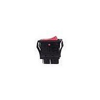
SWITCH ROCKER TV5 SPST VERT RED
Manufacturer
NKK Switches
Series
JWr
Type
Internationally Approved TV Rated Rockers, High Inrush 10, 16 Ampr
Datasheet
1.AT4126.pdf
(9 pages)
Specifications of JWM11BC2A-H
Circuit
SPST
Switch Function
On-Off
Contact Rating @ Voltage
10A @ 125VAC
Illumination
Non-Illuminated
Mounting Type
Panel Mount, Snap-In
Termination Style
Solder, Quick Connect - .110" (2.8mm)
Panel Cutout Dimensions
24.00mm x 15.40mm
Contact Form
SPST
Contact Rating
10 Amps at 125 VoltsAC, 250 VoltsAC
Actuator
Rocker, with Barrier
Mounting Style
Panel
Terminal Seal
Epoxy
Contact Plating
Silver
Features
Industry's first molded rocker with TV rating, with gray barrier, black housing; designed to handle large inrush current
Voltage Rating Ac
125 Volts, 250 Volts
Pole Throw Configuration
SPST
Switch Configuration
ON None OFF
Actuator Style
Rocker
Actuator Material
Polyphenylene Ether
Current Rating (max)
10A
Ac Voltage Rating (max)
250VVAC
Mechanical Life
25000
Contact Material
Silver Alloy
Housing Material
Melamine/Polyamide
Product Height (mm)
33.6mm
Product Depth (mm)
22.2mm
Product Length (mm)
30mm
Operating Temp Range
-25C to 70C
Terminal Type
Quick Connect/Solder Lug
Lead Free Status / RoHS Status
Lead free / RoHS Compliant
Illumination Type, Color
-
Illumination Voltage (nominal)
-
Lead Free Status / Rohs Status
Lead free / RoHS Compliant


B
Series JW
B48
Operating Environment
• Do not install switch where heavy dust collection occurs. Dust build-up under rocker may affect switch actuation.
• Do not actuate switch if submerged in water or oil.
• Installation is not recommended on horizontal surface in an environment where frequent splashing of
Panel Mounting
• Before snapping a switch into the panel, align the gasket evenly under bezel of the switch.
• When mounting into a panel, apply equal pressure to sides of bezel and insert parallel to panel.
• After mounting a switch, be sure there are no gaps between switch and panel.
• After installing into panel, do not apply excessive force.
• After panel installation and wiring is completed, do not apply force horizontally
• Behind the panel, cut area should be squared. If front of panel is painted, do not allow any paint to collect in
• Avoid reinstalling a switch once it has been mounted in a panel. This may cause deterioration of panel sealability.
water may occur. In such an environment, a minimum 30° angle installation is advisable. If there is
a possibility of freezing, install vertically so no moisture will be retained within switch housing.
Lightly push into panel.
or vertically from behind panel.
corners of cutout to prevent level mounting.
PRECAUTIONS FOR HANDLING & STORAGE FOR JWMW/LW (PANEL SEAL TYPES)
www.nkk.com
High Inrush 10 & 16 Amp Rockers
Incorrect
Correct
Clean Edges
30°
Related parts for JWM11BC2A-H
Image
Part Number
Description
Manufacturer
Datasheet
Request
R

Part Number:
Description:
Rocker Switches & Paddle Switches High In-rush Rated Rocker Switch
Manufacturer:
NKK Switches
Datasheet:
Part Number:
Description:
Rocker Switches & Paddle Switches High In-rush Rated Rocker Switch
Manufacturer:
NKK Switches
Datasheet:
Part Number:
Description:
Rocker Switches & Paddle Switches High In-rush Rated Rocker Switch
Manufacturer:
NKK Switches
Datasheet:
Part Number:
Description:
Rocker Switches & Paddle Switches High In-rush Rated Rocker Switch
Manufacturer:
NKK Switches
Datasheet:

Part Number:
Description:
Pushbutton Switches SPST ON(OFF) 15/32'
Manufacturer:
NKK Switches
Datasheet:

Part Number:
Description:
Pushbutton Switches SPST OFF(ON) 15/32'
Manufacturer:
NKK Switches
Datasheet:

Part Number:
Description:
Pushbutton Switches ON(OFF) NORM CLSD 3A RED PLNGR LUG 15/32
Manufacturer:
NKK Switches
Datasheet:

Part Number:
Description:
Pushbutton Switches SPDT ON-(ON)
Manufacturer:
NKK Switches
Datasheet:

Part Number:
Description:
Pushbutton Switches ON-(ON) RND BUSH MNT RED LED RED/RED CAP
Manufacturer:
NKK Switches
Datasheet:
Part Number:
Description:
Pushbutton Switches SPST ON-(OFF) STRT
Manufacturer:
NKK Switches
Datasheet:
Part Number:
Description:
Pushbutton Switches OFF(ON) NORM OPEN 3A RED CAP LUG 15/32
Manufacturer:
NKK Switches
Datasheet:
Part Number:
Description:
Pushbutton Switches ILLUM PUSHBUTTON SPDT
Manufacturer:
NKK Switches
Datasheet:
Part Number:
Description:
Pushbutton Switches OFF(ON) NORM OPEN 3A BLK CAP LUG 15/32
Manufacturer:
NKK Switches
Datasheet:
Part Number:
Description:
Pushbutton Switches SPST NO Metric Thrd Blk Plunge w/Blu Cap
Manufacturer:
NKK Switches
Datasheet:
Part Number:
Description:
Pushbutton Switches SPST OFF-(ON) NO 3A
Manufacturer:
NKK Switches
Datasheet: