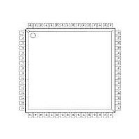
XRT5894IV-F Exar Corporation, XRT5894IV-F Datasheet - Page 4

XRT5894IV-F
Manufacturer Part Number
XRT5894IV-F
Description
IC LIU E1 QUAD 64TQFP
Manufacturer
Exar Corporation
Datasheet
1.XRT5894IVTR-F.pdf
(19 pages)
Specifications of XRT5894IV-F
Maximum Operating Temperature
+ 85 C
Maximum Power Dissipation
590 mW / 1240 mW
Minimum Operating Temperature
- 40 C
Mounting Style
SMD/SMT
Operating Supply Voltage
3.3 V / 5 V
Package / Case
TQFP-64
Supply Voltage Range
3.135V To 3.465V, 4.75V To 5.25
Power Dissipation Pd
1240mW
Operating Temperature Range
-40°C To +85°C
Digital Ic Case Style
TQFP
No. Of Pins
64
Filter Terminals
SMD
Rohs Compliant
Yes
Lead Free Status / RoHS Status
Lead free / RoHS Compliant
Lead Free Status / RoHS Status
Lead free / RoHS Compliant, Lead free / RoHS Compliant
Available stocks
Company
Part Number
Manufacturer
Quantity
Price
Company:
Part Number:
XRT5894IV-F
Manufacturer:
EXAR
Quantity:
1 558
Company:
Part Number:
XRT5894IV-F
Manufacturer:
Exar Corporation
Quantity:
10 000
Part Number:
XRT5894IV-F
Manufacturer:
EXAR/艾科嘉
Quantity:
20 000
PIN DESCRIPTION
Note:
1
Pin #
XRT5894
Has internal pull-up 50KW resistor.
10
12
13
14
15
16
17
18
19
20
21
22
23
24
25
26
27
28
29
30
31
32
33
34
11
1
2
3
4
5
6
7
8
9
Rev. 1.10
RXPOS1
RXNEG1
TXNEG2
RXPOS2
RXNEG2
RXNEG3
RXPOS3
TXNEG3
TXPOS2
LOSSEL
TXPOS3
RRING1
RRING2
TXCLK2
TXCLK3
RRING3
Symbol
TRING2
RTIP1
TTIP2
RTIP2
RTIP3
LOS1
LOS2
LOS3
GND
GND
GND
GND
V
V
V
V
V
NC
CC
CC
CC
CC
CC
Type
O
O
O
O
O
O
O
O
O
O
O
I
I
I
I
I
I
I
I
I
I
I
I
I
Description
Receiver 1 Loss of Signal. Asserted during LOS condition.
Receiver 1 Positive Data Out. Positive RZ data output for channel 1.
Receiver 1 Negative Data Out. Negative RZ data output for channel 1.
Positive Supply (+3.3V or +5.0V + 5%). Digital circuitry.
Receiver 1 Positive Bipolar Input.
Receiver 1 Negative Bipolar Input.
Positive Supply (+3.3V or +5.0V + 5%). Analog circuitry.
Analog Ground.
Positive Supply. (+3.3V or +5.0V + 5%). Analog circuitry.
Analog Ground.
Transmitter 2 Negative Bipolar Output.
Positive Supply (+3.3V or +5.0V + 5%). Transmitter channel 2.
Transmitter 2 Positive Bipolar Output.
Analog Ground. Transmitter channel 2.
Receiver 2 Positive Bipolar Input.
Receiver 2 Negative Bipolar Input.
Transmitter 2 Clock Input. Use for clocked mode with NRZ data.
Transmitter 2 Negative Data Input. Negative NRZ or RZ data input.
Transmitter 2 Positive Data Input. Positive NRZ or RZ data input.
Receiver 2 Loss of Signal. Asserted during LOS condition.
Receiver 2 Positive Data Out. Positive RZ data output for channel 2.
Receiver 2 Negative Data Out. Negative RZ data output for channel 2.
Positive Supply (+3.3V or +5.0V + 5%). Digital circuitry.
No Connect.
Loss of Signal Delay Select. “Hi” selects G.775, “Lo” selects user programmable.
Digital Ground.
Receiver 3 Negative Data Out. Negative RZ data output for channel 3.
Receiver 3 Positive Data Out. Positive RZ data output for channel 3.
Receiver 3 Loss of Signal. Asserted during LOS condition.
Transmitter 3 Positive Data Input. Positive NRZ or RZ data input.
Transmitter 3 Negative Data Input. Negative NRZ or RZ data input.
Transmitter 3 Clock Input. Use for clocked mode with NRZ data.
Receiver 3 Negative Bipolar Input.
Receiver 3 Positive Bipolar Input.
4
1
1
1
1
1
1
1


