TMOV25SP750M Littelfuse Inc, TMOV25SP750M Datasheet - Page 20
TMOV25SP750M
Manufacturer Part Number
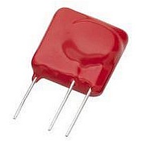
TMOV25SP750M
Description
TMOV VARISTOR PB FREE 25S
Manufacturer
Littelfuse Inc
Series
iTMOV®r
Specifications of TMOV25SP750M
Varistor Voltage
1320V (1.32kV)
Current-surge
20kA
Number Of Circuits
1
Maximum Ac Volts
750VAC
Energy
670J
Package / Case
Disc 25mm 3-Lead
Suppressor Type
Varistor
Peak Surge Current @ 8/20µs
20000A
Varistor Case
25mm DISC
Clamping Voltage Vc Max
1950V
Peak Energy (10/1000us)
670J
Voltage Rating Vdc
1320V
Voltage Rating Vac
750V
Lead Free Status / RoHS Status
Lead free / RoHS Compliant
Maximum Dc Volts
-
Lead Free Status / Rohs Status
Lead free / RoHS Compliant


Nominal Varistor Region of Operation
The varistor characteristic follows the equation:
I = kV
defines the degree of nonlinearity. Alpha is a figure of merit
and can be determined from the slope of the V-I curve or
calculated from the formula:
In this region the varistor is conducting and R
dominate over C, R
magnitude less than R
During conduction the varistor voltage remains relatively
constant for a change in current of several orders of mag-
nitude. In effect, the device resistance, R
response to current. This can be observed by examining
the static or dynamic resistance as a function of current.
The static resistance is defined by:
and the dynamic resistance by:
Plots of typical resistance values vs current (I) are given in
Figure 16A and 16B.
FIGURE 15. EQUIVALENT CIRCUIT AT VARISTOR CONDUCTION
FIGURE 16A. R
a
0.05
0.01
, where (k) is a constant and the exponent (
500
100
0.5
0.1
50
10
0
5
1
0 .
Z
R
1
X
X
=
=
=
=
X
dv
------
V
--- -
di
------------------------------ -
log
------------------------------ - for I
log
I
STATIC VARISTOR RESISTANCE FIGURE
log
=
(
(
ON
(
V
V
0
I
1
V
2
2
2
1 .
and R
OFF
⁄
⁄
⁄
⁄
PEAK CURRENT (A)
I
V
V
1
1
1
I
)
but remains larger than R
)
)
=
OFF
L
R
R
. R
X
X
2
⁄
⁄
1
X
I
1
becomes many orders of
=
1
X
, is changing in
10
X
will pre-
a
ON
)
.
Revision: November 5, 2009
1
Varistor Products
0
0
16
Upturn Region of Operation
At high currents, approaching the maximum rating, the
varistor approximates a short-circuit. The curve departs
from the nonlinear relation and approaches the value of the
material bulk resistance, about 1Ω-10Ω. The upturn takes
place as R
represents the bulk resistance of the Z
tance is linear (which appears as a steeper slope on the log
plot) and occurs at currents 50A to 50,000A, depending on
the varistor size.
FIGURE 17. EQUIVALENT CIRCUIT AT VARISTOR UPTURN
FIGURE 16B. Z
0.005
0.001
0
0.01
0.05
.
0.5
01
5
1
0.01
X
approaches the value of R
X
DYNAMIC VARISTOR RESISTANCE
0.1
Please refer to www.littelfuse.com for current information.
PEAK CURRENT (A)
Specifications are subject to change without notice.
L
R
ON
1.0
ON
N
. Resistor R
O grains. This resis-
10
©2009 Littelfuse, Inc.
ON
100
Related parts for TMOV25SP750M
Image
Part Number
Description
Manufacturer
Datasheet
Request
R

Part Number:
Description:
FUSEHOLDER 20A MINI INLINE CRIMP
Manufacturer:
Littelfuse Inc
Datasheet:

Part Number:
Description:
FUSEHOLDER BODY ATO INLINE PNLMT
Manufacturer:
Littelfuse Inc
Datasheet:

Part Number:
Description:
FUSE 2A 63V FAST 1206
Manufacturer:
Littelfuse Inc
Datasheet:
Part Number:
Description:
FUSE 1.25A 63V FAST 1206
Manufacturer:
Littelfuse Inc
Datasheet:
Part Number:
Description:
FUSE .250A 125V FAST 1206
Manufacturer:
Littelfuse Inc
Datasheet:
Part Number:
Description:
FUSE 4A 32V FAST 1206
Manufacturer:
Littelfuse Inc
Datasheet:
Part Number:
Description:
FUSE 1.75A 63V FAST 1206
Manufacturer:
Littelfuse Inc
Datasheet:

Part Number:
Description:
FUSE 1A 32V FST 0603 LEADFREE TR
Manufacturer:
Littelfuse Inc
Datasheet:

Part Number:
Description:
FUSE 1A 32V FAST SLIM 0402
Manufacturer:
Littelfuse Inc
Datasheet:

Part Number:
Description:
FUSE 2A 125V FAST NANO2 SMD
Manufacturer:
Littelfuse Inc
Datasheet:

Part Number:
Description:
FUSE .250A 125V FAST NANO2 SMD
Manufacturer:
Littelfuse Inc
Datasheet:

Part Number:
Description:
FUSE .500A 125V FAST NANO2 SMD
Manufacturer:
Littelfuse Inc
Datasheet:

Part Number:
Description:
FUSE 1.5A 125V FAST NANO2 SMD
Manufacturer:
Littelfuse Inc
Datasheet:

Part Number:
Description:
FUSE 4A 125V FAST NANO2 SMD
Manufacturer:
Littelfuse Inc
Datasheet:

Part Number:
Description:
FUSE 1A 125V FAST NANO2 SMD
Manufacturer:
Littelfuse Inc
Datasheet: