TMOV25SP750M Littelfuse Inc, TMOV25SP750M Datasheet - Page 56
TMOV25SP750M
Manufacturer Part Number
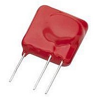
TMOV25SP750M
Description
TMOV VARISTOR PB FREE 25S
Manufacturer
Littelfuse Inc
Series
iTMOV®r
Specifications of TMOV25SP750M
Varistor Voltage
1320V (1.32kV)
Current-surge
20kA
Number Of Circuits
1
Maximum Ac Volts
750VAC
Energy
670J
Package / Case
Disc 25mm 3-Lead
Suppressor Type
Varistor
Peak Surge Current @ 8/20µs
20000A
Varistor Case
25mm DISC
Clamping Voltage Vc Max
1950V
Peak Energy (10/1000us)
670J
Voltage Rating Vdc
1320V
Voltage Rating Vac
750V
Lead Free Status / RoHS Status
Lead free / RoHS Compliant
Maximum Dc Volts
-
Lead Free Status / Rohs Status
Lead free / RoHS Compliant


For automotive 24V and 42V applications please contact your Littelfuse representative or visit www.littelfuse.com for the latest product
update.
NOTES:
1. Average power dissipation of transients not to exceed 0.1W, 0.15W, 0.3W and 1W for model sizes 1206, 1210, 1812 and 2220 respectively.
2. Load Dump energy rating (into the suppressor) of a voltage transient with a resultant time constant of 115ms to 230ms.
3. Thermal shock capability per Mil-Std-750, Method 1051: -55ºC to 125ºC, 5 minutes at 25ºC, 25 Cycles: 15 minutes at each extreme.
4. For application specific requirements, please contact Littelfuse.
AUML Varistor Series
V18AUMLA1206
V18AUMLA1210
V18AUMLA1812
V18AUMLA2220
Maximum Leakage Current/Clamping Voltage Curve for
AUML Series at 25ºC
Device Ratings and Specifications
Current, Energy and Power Derating Curve
When transients occur in rapid succession, the average
power dissipation is the energy (watt-seconds) per pulse
times the number of pulses per second. The power so
developed must be within the specifications shown on the
Device Ratings and Characteristics Table for the specific
device. Certain parameter ratings must be derated at high
temperatures as shown below.
Figure 3
100
Figure 1
10
1
Part Number
1210/1206
1812
2220
100
10μA
90
80
70
60
50
40
30
20
10
0
-55
MAXIMUM LEAKAGE
Surface Mount Multilayer Varistors (MLVs) > AUML Series
50
100μA
60
Continuous
DC Voltage
Maximum
AMBIENT TEMPERATURE (
1mA
V
70
(V)
M(DC)
18
18
18
18
Maximum Ratings (125
80
10mA
CURRENT
90
Jump Start
100 110
100mA
Voltage
(5 Min)
V
24.5
24.5
24.5
24.5
(V)
MAXIMUM CLAMPING VOLTAGE
JUMP
o
C)
1A
120 130
Load Dump
10A
(10 Pulses)
ºC
Energy
140 150
)
W
3.0
6.0
(J)
1.5
25
100A
LD
1210/1206
1812
2220
Revision: November 5, 2009
Varistor Products
Nominal Varistor Voltage
V
52
N(DC)
(V)
23
23
23
23
DC Test Current
Min
Figure 2
Peak Pulse Current Test Waveform for Clamping Voltage
Typical V-I Characteristics of the V18AUMLA2220 at -40ºC,
25ºC, 85ºC and 125ºC
Figure 4
100
at 10mA
10
1
O
1
100
0
T = Time from 10% to 90% of Peak
T
T
Example - For an 8/20 μs Current Waveform:
50
0
1μA
1
V
1
2
= Virtual Origin of Wave
N(DC)
= Rise Time = 1.25 x T
= Decay Time
125
-40
25
85
o
o
o
o
(V)
8μs = T
20μs = T
C
C
32
32
32
32
C
C
Max
10μA
Please refer to www.littelfuse.com/series/AUML.html for current information.
T
Specifications (25
T
1
1
100μA
2
= Rise Time
Standby Leakage
= Decay Time
T
2
(at 13V DC)
Maximum
1mA
(μA)
200
100
50
50
I
CURRENT
L
Specifications are subject to change without notice.
10mA
ºC
100mA
)
Maximum Clamping
Test Current (8/20μs)
1A
(V)
V
40
40
40
40
Voltage (V
C
10A
©2009 Littelfuse, Inc.
100A
C
) at
10.0
TIME
(A)
5.0
1.5
1.5
I
P
1000A
Related parts for TMOV25SP750M
Image
Part Number
Description
Manufacturer
Datasheet
Request
R

Part Number:
Description:
FUSEHOLDER 20A MINI INLINE CRIMP
Manufacturer:
Littelfuse Inc
Datasheet:

Part Number:
Description:
FUSEHOLDER BODY ATO INLINE PNLMT
Manufacturer:
Littelfuse Inc
Datasheet:

Part Number:
Description:
FUSE 2A 63V FAST 1206
Manufacturer:
Littelfuse Inc
Datasheet:
Part Number:
Description:
FUSE 1.25A 63V FAST 1206
Manufacturer:
Littelfuse Inc
Datasheet:
Part Number:
Description:
FUSE .250A 125V FAST 1206
Manufacturer:
Littelfuse Inc
Datasheet:
Part Number:
Description:
FUSE 4A 32V FAST 1206
Manufacturer:
Littelfuse Inc
Datasheet:
Part Number:
Description:
FUSE 1.75A 63V FAST 1206
Manufacturer:
Littelfuse Inc
Datasheet:

Part Number:
Description:
FUSE 1A 32V FST 0603 LEADFREE TR
Manufacturer:
Littelfuse Inc
Datasheet:

Part Number:
Description:
FUSE 1A 32V FAST SLIM 0402
Manufacturer:
Littelfuse Inc
Datasheet:

Part Number:
Description:
FUSE 2A 125V FAST NANO2 SMD
Manufacturer:
Littelfuse Inc
Datasheet:

Part Number:
Description:
FUSE .250A 125V FAST NANO2 SMD
Manufacturer:
Littelfuse Inc
Datasheet:

Part Number:
Description:
FUSE .500A 125V FAST NANO2 SMD
Manufacturer:
Littelfuse Inc
Datasheet:

Part Number:
Description:
FUSE 1.5A 125V FAST NANO2 SMD
Manufacturer:
Littelfuse Inc
Datasheet:

Part Number:
Description:
FUSE 4A 125V FAST NANO2 SMD
Manufacturer:
Littelfuse Inc
Datasheet:

Part Number:
Description:
FUSE 1A 125V FAST NANO2 SMD
Manufacturer:
Littelfuse Inc
Datasheet: