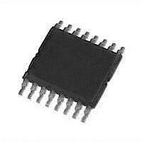
ZXLD1370EST16TC Diodes Inc, ZXLD1370EST16TC Datasheet - Page 30

ZXLD1370EST16TC
Manufacturer Part Number
ZXLD1370EST16TC
Description
LED Drivers 6V TO 60V 11uA
Manufacturer
Diodes Inc
Datasheet
1.ZXLD1370EST16TC.pdf
(36 pages)
Specifications of ZXLD1370EST16TC
High Level Output Current
18 mA
Operating Supply Voltage
6 V to 60 V
Maximum Supply Current
11 uA
Maximum Operating Temperature
+ 125 C
Package / Case
TSSOP-16 EP
Minimum Operating Temperature
- 40 C
Lead Free Status / RoHS Status
Lead free / RoHS Compliant
Lead Free Status / RoHS Status
Lead free / RoHS Compliant
Available stocks
Company
Part Number
Manufacturer
Quantity
Price
Company:
Part Number:
ZXLD1370EST16TC
Manufacturer:
MICROCHIP
Quantity:
2 000
ZXLD1370
Document number: DS32165 Rev. 4 - 2
Applications Information
PCB Layout considerations
PCB layout is a fundamental activity to get the most of the device in all configurations. In the following section it is possible
to find some important insight to design with the ZXLD1370 both in Buck and Buck-Boost/Boost configurations.
Here are some considerations useful for the PCB layout:
APPLICATION EXAMPLES
Example 1:
2.8A Buck LED driver
In this application example, the ZXLD1370 is connected as a buck LED driver. The schematic and parts list are shown
below. The LED driver is able to deliver 2.8A of LED current with an input voltage range of 8V to 24V. In order to achieve
high efficiency at high LED current, a Super Barrier Rectifier (SBR) with a low forward voltage is used as the free wheeling
rectifier.
This LED driver is suitable for applications which require high LED current such as LED projector, automatic LED lighting
etc.
Inductor, Switch
and
Freewheeling
diode
placed as close together as possible.
than 5mm from the SHP pin.
2.2uF, X7R, 100V (C3 and C4). In addition to these capacitors, it is suggested to add two ceramic capacitors of
1uF, X7R, 100V each (C2, C8), as well as a further decoupling capacitor of 100nF close to the VIN/VAUX pins (C9).
VIN and VAUX pins can be short-circuited when the device is used in buck mode, or can be driven from a separate
supply.
In order to avoid ringing due to stray inductances, the inductor L1, the anode of D1 and the drain of Q1 should be
The shaping capacitor C1 is fundamental for the stability of the control loop. To this end it should be placed no more
Input voltage pins, VIN and VAUX, need to be decoupled. It is recommended to use two ceramic capacitors of
(Continued)
Figure 39: Circuit Layout
www.diodes.com
30 of 36
Diodes Incorporated
A Product Line of
SHP pin
V
decoupling
IN
/ V
© Diodes Incorporated
ZXLD1370
AUX
March 2011


