TEMD6010FX01 Vishay, TEMD6010FX01 Datasheet - Page 2
TEMD6010FX01
Manufacturer Part Number
TEMD6010FX01
Description
Photodiodes 16V 100mW 540nm
Manufacturer
Vishay
Type
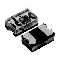
Silicon PIN Photodioder
Specifications of TEMD6010FX01
Photodiode Material
Silicon
Peak Wavelength
540 nm
Maximum Reverse Voltage
16 V
Maximum Power Dissipation
100 mW
Maximum Light Current
1 uA
Maximum Dark Current
30 nA
Package / Case
SMD-3
Maximum Operating Temperature
+ 100 C
Minimum Operating Temperature
- 40 C
Wavelength Typ
540nm
Half Angle
60°
Dark Current
2nA
Diode Case Style
1206
No. Of Pins
2
Operating Temperature Range
-40°C To +100°C
Msl
MSL 4 - 72 Hours
Reverse Voltage Vr
16V
Wavelength
540nm
Output Type
Current On Typ, 1µA
Photodiode Type
PIN
Polarity
Forward
Dark Current (max)
30nA
Power Dissipation
100mW
Operating Temp Range
-40C to 100C
Operating Temperature Classification
Industrial
Mounting
Surface Mount
Pin Count
3
Package Type
SMD
Lead Free Status / RoHS Status
Lead free / RoHS Compliant
Lead Free Status / RoHS Status
Lead free / RoHS Compliant, Lead free / RoHS Compliant


TEMD6010FX01
Vishay Semiconductors
Note
T
BASIC CHARACTERISTICS
T
www.vishay.com
2
amb
amb
BASIC CHARACTERISTICS
PARAMETER
Breakdown voltage
Reverse dark current
Diode capacitance
Reverse light current
Temperature coefficient of I
Angle of half sensitivity
Wavelength of peak sensitivity
Range of spectral bandwidth
= 25 °C, unless otherwise specified
Fig. 1 - Reverse Dark Current vs. Ambient Temperature
= 25 °C, unless otherwise specified
Fig. 2 - Reverse Light Current vs. Illuminance
18818
20093
0.001
0.01
1000
0.01
0.1
100
10
0.1
10
1
1
10
0
T
amb
20
- Ambient Temperature (°C)
E
V
100
- Illuminance (lx)
ra
40
CIE illuminant A
V
For technical questions, contact:
60
R
1000
= 5 V
V
E
E
E
V
V
R
V
V
e
R
R
80
= 5 V
= 100 lx, CIE illuminant A,
= 100 lx, CIE illuminant A,
= 1 mW/cm
= 0 V, f = 1 MHz, E = 0 lx
= 5 V, f = 1 MHz, E = 0 lx
I
TEST CONDITION
R
V
CE
= 100 µA, E = 0 lx
10000
100
= 5 V, E = 0 lx
V
V
V
Ambient Light Sensor
R
R
R
= 5 V
= 5 V
= 5 V
2
, λ = 550 nm,
detectortechsupport@vishay.com
SYMBOL
V
TK
λ
C
C
(BR)
I
I
I
λ
ϕ
0.5
ro
ra
ra
Fig. 4 - Relative Spectral Sensitivity vs. Wavelength
D
D
p
Ira
Fig. 3 - Diode Capacitance vs. Reverse Voltage
20047
20094
1.0
0.8
0.6
0.4
0.2
0.0
70
60
50
40
30
20
10
0
400
0
MIN.
0.03
16
600
Wavelength (nm)
V
10
430 to 610
R
- Reverse Voltage (V)
TYP.
0.04
± 60
540
0.2
60
24
2
1
800
20
Document Number: 81308
Photodiode
human eye
E
f = 1 MHz
MAX.
0
1000
= 0
30
Rev. 1.5, 24-Sep-09
30
UNIT
%/K
deg
nm
nm
nA
pF
pF
µA
µA
V
Related parts for TEMD6010FX01
Image
Part Number
Description
Manufacturer
Datasheet
Request
R

Part Number:
Description:
357-036-542-201 CARDEDGE 36POS DL .156 BLK LOPRO
Manufacturer:
Vishay
Datasheet:
Part Number:
Description:
357-036-542-201 CARDEDGE 36POS DL .156 BLK LOPRO
Manufacturer:
Vishay
Datasheet:
Part Number:
Description:
357-036-542-201 CARDEDGE 36POS DL .156 BLK LOPRO
Manufacturer:
Vishay
Datasheet:
Part Number:
Description:
357-036-542-201 CARDEDGE 36POS DL .156 BLK LOPRO
Manufacturer:
Vishay
Datasheet:
Part Number:
Description:
357-036-542-201 CARDEDGE 36POS DL .156 BLK LOPRO
Manufacturer:
Vishay
Datasheet:
Part Number:
Description:
357-036-542-201 CARDEDGE 36POS DL .156 BLK LOPRO
Manufacturer:
Vishay
Datasheet:
Part Number:
Description:
357-036-542-201 CARDEDGE 36POS DL .156 BLK LOPRO
Manufacturer:
Vishay
Datasheet:
Part Number:
Description:
357-036-542-201 CARDEDGE 36POS DL .156 BLK LOPRO
Manufacturer:
Vishay
Datasheet:
Part Number:
Description:
357-036-542-201 CARDEDGE 36POS DL .156 BLK LOPRO
Manufacturer:
Vishay
Datasheet:
Part Number:
Description:
357-036-542-201 CARDEDGE 36POS DL .156 BLK LOPRO
Manufacturer:
Vishay
Datasheet:
Part Number:
Description:
357-036-542-201 CARDEDGE 36POS DL .156 BLK LOPRO
Manufacturer:
Vishay
Datasheet:
Part Number:
Description:
357-036-542-201 CARDEDGE 36POS DL .156 BLK LOPRO
Manufacturer:
Vishay
Datasheet:
Part Number:
Description:
357-036-542-201 CARDEDGE 36POS DL .156 BLK LOPRO
Manufacturer:
Vishay
Datasheet:
Part Number:
Description:
357-036-542-201 CARDEDGE 36POS DL .156 BLK LOPRO
Manufacturer:
Vishay
Datasheet:
Part Number:
Description:
357-036-542-201 CARDEDGE 36POS DL .156 BLK LOPRO
Manufacturer:
Vishay
Datasheet: