E3S-CR11 Omron, E3S-CR11 Datasheet - Page 13
E3S-CR11
Manufacturer Part Number
E3S-CR11
Description
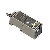
Industrial Photoelectric Sensors POLAR RETROREFLECTIV
Manufacturer
Omron
Type
Long Range Metal Body Sensorr
Series
E3S-Cr
Specifications of E3S-CR11
Features
Mutual interference protection
Height
29.5 mm
Length
50 mm
Maximum Operating Temperature
+ 55 C
Minimum Operating Temperature
- 25 C
Operating Supply Voltage
10 V to 30 V
Width
40.4 mm
Sensing Distance
3000 mm
Output Configuration
NPN or PNP
Sensing Range
0m To 3m
Output Current
100mA
Supply Voltage Range Dc
10V To 30V
Sensor Housing
Rectangular
Sensor Input
Optical
Sensing Range Max
3m
Switch Terminals
Wire Leaded
Svhc
Bis (2-ethyl(hexyl)phthalate) (DEHP) (15-Dec-2010)
Output Type
NPN / PNP Selectable
Response Time
1ms
Svhc (secondary)
Benzyl Butyl Phthalate (BBP) (15-Dec-2010)
Rohs Compliant
Yes
Connector Type
2m Cable
Current Consumption
40mA
External Depth
50mm
External Length / Height
23mm
External Width
20.4mm
Ip/nema Rating
IP67
Sensing Method
Retroreflective, Polarized
Sensing Object
Mirror
Sensing Light
Red
Mounting Type
Bracket Mount, Horizontal
Current - Supply
40mA
Voltage - Supply
10 V ~ 30 V
Package / Case
Module, Pre-Wired
Lead Free Status / RoHS Status
Lead free / RoHS Compliant
Lead Free Status / RoHS Status
Lead free / RoHS Compliant, Lead free / RoHS Compliant
Available stocks
Company
Part Number
Manufacturer
Quantity
Price
Company:

Part Number:
E3S-CR11-M1J
Manufacturer:
PIR
Quantity:
8 460


Precautions
J CONNECTION
If the input/output lines of the photoelectric sensor are placed in the
same conduit or duct as power lines or high-voltage lines, the photo-
electric sensor could be induced to malfunction, or be damaged, by
the electrical noise. Either separate the wiring, or use shielded lines
as input/output lines to the photoelectric sensor.
The cord connected to the E3S-C can be extended up to 100 m pro-
vided that the diameter of each wire of the cord is 0.3 mm
J POWER SUPPLY
If the standard switching regulator is used as a power supply, the
frame ground (FG) terminal and the ground (G) terminal, on the
power supply, must be grounded. If this is not done the E3S-C may
malfunction, due to the switching noise of the power supply.
If an inverter motor or servomotor is used with the E3S-C, the frame
ground (FG) terminal and the ground (G) terminal, on the motor,
must be grounded, otherwise the E3S-C may malfunction.
Installation
J MOUNTING
Use M4 screws to mount the E3S-C. The tightening torque of each
screw must be 12 kgf S m (1.18 N S m) maximum.
J DIRECT MOUNTING
Mount the E3S-C as shown in the following illustrations.
E3S-C
M4
M4 hole
M4 hole
Two, M3
Two, 4.5 dia.
through holes
M4 hole
M4 hole
M3
2
minimum.
J WATER RESISTANCE
To ensure the water resistance of the E3S-C, tighten the screws of
the operation panel cover to a torque of 3.5 to 5.5 kgf S cm (0.34 N S
m to 0.54 N S m).
J OPTICAL AXIS OF THROUGH-BEAM
The E3S-C through-beam models incorporate two lenses, one of
which will be used as shown in the following illustration. When using
a slit, the slit must be on the side where the lens is located.
SENSOR
Lens in use. The slit
must be on this side.
Lens not in use.
E3S-C
13
Related parts for E3S-CR11
Image
Part Number
Description
Manufacturer
Datasheet
Request
R

Part Number:
Description:
SENSOR PHOTO HORZ 98' THRUBEAM
Manufacturer:
Omron
Datasheet:

Part Number:
Description:
SENSOR PHOTO VERT 98' THRUBEAM
Manufacturer:
Omron
Datasheet:

Part Number:
Description:
HOR, T-BEAM 30M CONN.
Manufacturer:
Omron
Datasheet:
Part Number:
Description:
VERTICAL, T-BEAM 30M CONN.
Manufacturer:
Omron
Datasheet:
Part Number:
Description:
Industrial Photoelectric Sensors DIFFUSE REFLECTIVE
Manufacturer:
Omron
Datasheet:
Part Number:
Description:
Photoelectric Sensor
Manufacturer:
Omron
Datasheet:

Part Number:
Description:
Photoelectric Sensor
Manufacturer:
Omron
Datasheet:
Part Number:
Description:
Photoelectric Sensors - Industrial DIFFUSE REFLECTIVE
Manufacturer:
Omron
Datasheet:

Part Number:
Description:
Photoelectric Sensors - Industrial PHOTOELECTRIC SENSOR NC/NR
Manufacturer:
Omron

Part Number:
Description:
Photoelectric Sensors - Industrial 2M DIFFUSE NPN/PNP VERT
Manufacturer:
Omron
Datasheet:


Part Number:
Description:
G6S-2GLow Signal Relay
Manufacturer:
Omron Corporation
Datasheet:
Part Number:
Description:
Compact, Low-cost, SSR Switching 5 to 20 A
Manufacturer:
Omron Corporation
Datasheet:
Part Number:
Description:
Manufacturer:
Omron Corporation
Datasheet: