STM32-P103 Olimex Ltd., STM32-P103 Datasheet
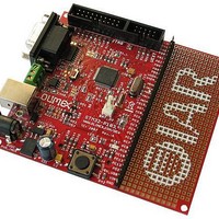
STM32-P103
Specifications of STM32-P103
Available stocks


Related parts for STM32-P103


STM32-P103 Summary of contents
Page 1
STM-P103 development board Copyright(c) 2008, OLIMEX Ltd, All rights reserved Rev.A, April 2008 Users Manual ...
Page 2
... PCB: FR-4, 1.5 mm (0,062"), soldermask, silkscreen component print - Dimensions: 100 x 90mm (3.94 x 3.5") ELECTROSTATIC WARNING: The STM32-P103 board is shipped in protective anti-static packaging. The board must not be subject to high electrostatic potentials. General practice for working with static sensitive devices should be applied when working with this board. ...
Page 3
BOARD USE REQUIREMENTS: Cables: Hardware: ARM-JTAG, ARM-USB-OCD, ARM-USB-TINY or other ARM Software: BOARD LAYOUT: 1.8 meter USB A-B cable to connect to USB host. JTAG compatible tool ARM C compiler and debugger software, the possible options are: - free open ...
Page 4
SCHEMATIC: ...
Page 5
... PROCESSOR FEATURES: STM-P103 board use ARM 32-bit Cortex™-M3 CPU STM32F103RBT6 from ST Microelectronics with these features: - CPU clock up to 72Mhz - FLASH 128KB - RAM 20KB - DMA x7 channels - RTC - WDT - Timers x3+1 - SPI x2 - I2C x2 - USART x3 - USB x1 - CAN x1 (multiplexed with USB so both can't be used in same time) ...
Page 6
MEMORY MAP: ...
Page 7
... STM32F103RBT6 in power sleep mode and in these modes the consumption of the MCU is only few micro ampers. RESET CIRCUIT: STM32-P103 reset circuit is made with RC group R8 - 10K and C28 - 100nF. Although on the schematic is made provision for external reset IC such is not necessary as STM32 have build-in brown out detector. Manual reset is possible by the RESET button ...
Page 8
... Connects 3.3V to STM32F103RBT6 Vbat pin.1 Default state closed (shorten), Vbat signal is also available to BAT_3V connector you want to connect external backup battery to the STM32F103RBT6 this jumper should be opened (unshorted) and the external battery to be connected to BAT_3V connector(see connector description for BAT_3V connector pining.).VBAT accept 2 - 3.6V. ...
Page 9
... Multi Media Card. Log PC6 – MMC no write protected . Log.0 of PC7 – MMC is write protected. Default state closed (shorten) MCU_E Connect 3.3V regulated voltage to STM32F103RBT6 3.3V_ power pins. 3.3V_MCU_E jumper is used if you need to measure current consumption of the microcontroller. Default state closed (shorten) ...
Page 10
... The JTAG connector allows the software debugger to talk via a JTAG (Joint Test Action Group) port directly to the core. Instructions may be inserted and executed by the core thus allowing STM32F103RBT6 memory to be programmed with code and executed step by step by the host software. For more details refer to IEEE Standard 1149.1 - 1990 Standard Test Access Port and Boundary Scan Architecture and STM32F103RBT6 datasheets and users manual ...
Page 11
... RxD GND SPI: STM32F103RBT6 have 2 SPIs which able to communicate Mbits/s in slave and master modes in fullduplex and simplex communication modes. The 3-bit prescaler gives 8 master mode frequencies and the frame is configurable generation/verification supports basic SD Card/MMC modes. Both SPIs can be served by the DMA controller. ...
Page 12
... STM32F103RBT6 have two I²C bus interfaces which can operate in multi- master and slave modes. They can support standard and fast modes. They support dual slave addressing (7-bit only) and both 7/10-bit addressing in master mode. A hardware CRC generation/verification is embedded. They can be served by DMA and they support SM Bus 2.0/PM Bus. ...
Page 13
... USBDP 4 GND ADC: STM32F103RBT6 have two 12-bit Analog to Digital Converters which share external channels, performing conversions in singleshot or scan modes. In scan mode, automatic conversion is performed on a selected group of analog inputs. Additional logic functions embedded in the ADC interface allow: - Simultaneous sample and hold ...
Page 14
MECHANICAL DIMENSIONS: AVAILABLE DEMO SOFTWARE: DEMO1. DEMO2. starts moving the mouse cursor in circle. DEMO3. Blinking LED for EW-ARM 5.11 Blinks the on-board LED. USB mouse for EW-ARM 5.11 Creates USB mouse and when board is connected ...
Page 15
... ORDER CODE: STM32-P103 How to order? You can order to us directly or by any of our distributors. Check our web All boards produced by Olimex are ROHS compliant Revision history: REV.A - create April 2008 – assembled and tested (no kit, no soldering required) www.olimex.com/dev for more info. ...
Page 16
... This document is intended only to assist the reader in the use of the product. OLIMEX Ltd. shall not be liable for any loss or damage arising from the use of any information in this document or any error or omission in such ...