ECG001B-G TriQuint, ECG001B-G Datasheet - Page 4
ECG001B-G
Manufacturer Part Number
ECG001B-G
Description
RF Amplifier DC-6 GHz 22dB Gain at 1 GHz
Manufacturer
TriQuint
Type
Buffer Amplifierr
Datasheet
1.ECG001B-PCB.pdf
(5 pages)
Specifications of ECG001B-G
Mounting Style
SMD/SMT
Number Of Channels
1
Operating Frequency
6000 MHz
Noise Figure
3.4 dB @ 2000 MHz
Operating Supply Voltage
3.4 V
Supply Current
30 mA (Typ) @ 5 V
Maximum Operating Temperature
+ 250 C
Minimum Operating Temperature
- 40 C
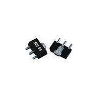
Package / Case
SOT-89
Lead Free Status / RoHS Status
Lead free / RoHS Compliant
Other names
1066897
Available stocks
Company
Part Number
Manufacturer
Quantity
Price
Company:

Part Number:
ECG001B-G
Manufacturer:
TriQuint
Quantity:
5 000
Part Number:
ECG001B-G
Manufacturer:
TRIQUIN
Quantity:
20 000


WJ Communications, Inc • Phone 1-800-WJ1-4401 • FAX: 408-577-6621 • e-mail: sales@wj.com • Web site: www.wj.com, www.TriQuint.com
This package is lead-free/Green/RoHS-compliant. The plating material on the leads is NiPdAu. It is compatible with both lead-free
E001G
XXXX
ECG001B
InGaP HBT Gain Block
(maximum 260 °C reflow temperature) and leaded (maximum 245 °C reflow temperature) soldering processes.
Outline Drawing
Land Pattern
ECG001B-G Mechanical Information
Specifications and information are subject to change without notice
The component will be marked with an
“E001G” designator with an alphanumeric lot
code on the top surface of the package.
obsolete tin-lead package is marked with an
“E001”
alphanumeric lot code; it may also have been
marked with a “B” designator followed by a 3-
digit numeric lot code.
Tape and reel specifications for this part are
located on the website in the “Application
Notes” section.
ESD Rating: Class 1A
Value:
Test:
Standard:
MSL Rating: Level 3 at +260 °C convection reflow
Standard:
1. Ground / thermal vias are critical for the proper performance of this
2. Add as much copper as possible to inner and outer layers near the
3. Mounting screws can be added near the part to fasten the board to a
4. Do not put solder mask on the backside of the PC board in the
5. RF trace width depends upon the PC board material and
6. Use 1 oz. Copper minimum.
7. All dimensions are in millimeters (inches). Angles are in degrees.
Mounting Config. Notes
device. Vias should use a .35mm (#80 / .0135”) diameter drill and
have a final plated thru diameter of .25 mm (.010”).
part to ensure optimal thermal performance.
heatsink. Ensure that the ground / thermal via region contacts the
heatsink.
region where the board contacts the heatsink.
construction.
MSL / ESD Rating
Product Marking
designator
Passes between 250 and 500V
Human Body Model (HBM)
JEDEC Standard JESD22-A114
JEDEC Standard J-STD-020
followed
Page 4 of 5 January 2008
by
The
an
Related parts for ECG001B-G
Image
Part Number
Description
Manufacturer
Datasheet
Request
R

Part Number:
Description:
Manufacturer:
TriQuint
Datasheet: