NTE966 NTE ELECTRONICS, NTE966 Datasheet

Replacement Semiconductors TO-220 +12V 1A

NTE966

Manufacturer Part Number
NTE966
Description
Replacement Semiconductors TO-220 +12V 1A
Manufacturer
NTE ELECTRONICS
Datasheet

Specifications of NTE966

Primary Input Voltage
19V
Output Voltage Fixed
12V
Dropout Voltage Vdo
2V
No. Of Outputs
1
No. Of Pins
3
Output Current
1A
Operating Temperature Range
-55°C To +150°C
Current Rating
1A
Rohs Compliant
Yes
Lead Free Status / RoHS Status
Lead free / RoHS Compliant
Lead Free Status / RoHS Status
Lead free / RoHS Compliant, Lead free / RoHS Compliant
The NTE966 fixed−voltage regulator is a monolithic integrated circuit in a TO220 type package de-
signed for use in a wide variety of applications including local, on−card regulation. This regulator em-
ploys internal current limiting, thermal shutdown, and safe−area compensation. With adequate heat-
sinking it can deliver output currents in excess of 1.0 ampere.
Features:
D Output Current in Excess of 1.0 Ampere
D No External Components Reguired
D Internal Thermal Overload Protection
D Internal Short−Circuit Current Limiting
D Output Transistor Safe−Area Compensation
Absolute Maximum Ratings: (T
Input Voltage, V
Power Dissipation (T
Thermal Resistance, Junction−to−Ambient, R
Thermal Resistance, Junction−to−Case, R
Operating Junction Temperature Range, T
Storage Junction Temperature Range, T
Electrical Characteristics: (V
Note 1. Load and line regulation are specified at constant junction temperature. Changes in V
Output Voltage
Line Regulation
Load Regulation
Derate above +25°C
Derate above +75°C
to heating effects must be taken into account separately. Pulse testing with low duty cycle
is used.
Parameter
in
. . . . . . . . . . . . . . . . . . . . . . . . . . . . . . . . . . . . . . . . . . . . . . . . . . . . . . . . . . . . . . . . .
3−Terminal Positive Voltage Regulator, 12V
A
C
= +25°C), P
= +25°C), P
. . . . . . . . . . . . . . . . . . . . . . . . . . . . . . . . . . . . . . . . . . . . . . . . . . .
. . . . . . . . . . . . . . . . . . . . . . . . . . . . . . . . . . . . . . . . . . . . . . . . . . . .
Symbol
Reg
Reg
V
in
O
load
line
= 19V, I
A
D
D
= +25°C unless otherwise specified)
Integrated Circuit
. . . . . . . . . . . . . . . . . . . . . . . . . . . . . . . . . . . . . .
. . . . . . . . . . . . . . . . . . . . . . . . . . . . . . . . . . . . . .
T
5mA ≤ I
T
T
J
J
J
= +25°C
= +25°C, Note 1
= +25°C, Note 1
stg
O
J
thJC
= 500mA, T
NTE966
O
. . . . . . . . . . . . . . . . . . . . . . . . . . . . . . . . . .
. . . . . . . . . . . . . . . . . . . . . . . . . . . . . . . . . .
≤ 1A, P
thJA
. . . . . . . . . . . . . . . . . . . . . . . . . . . . . . . . . . . . . . .
Test Conditions
. . . . . . . . . . . . . . . . . . . . . . . . . . . . . . . . . . . .
O
≤ 15W, 14.5V ≤ V
J
14.5V ≤ V
16V ≤ V
5mA ≤ I
250mA ≤ I
= 0° to +125°C unless otherwise specified)
O
in
≤ 1.5A
in
≤ 22V
O
≤ 20V
≤ 750mA
in
≤ 27V
11.5 12.0 12.5
11.4 12.0 12.6
Min
Typ
Internally Limited
Internally Limited
13
45
16
6
−55° to +150°C
−65° to +150°C
Max
240
120
160
15.4mW/°C
80
200mW/°C
65°C/W
5°C/W
35Vdc
Unit
O
mV
mV
mV
mV
V
V
due

Related parts for NTE966

NTE966 Summary of contents

Page 1

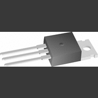
... Positive Voltage Regulator, 12V The NTE966 fixed−voltage regulator is a monolithic integrated circuit in a TO220 type package de- signed for use in a wide variety of applications including local, on−card regulation. This regulator em- ploys internal current limiting, thermal shutdown, and safe−area compensation. With adequate heat- sinking it can deliver output currents in excess of 1 ...

Page 2

... Normally good construction tech- niques should be used to minimize ground loops and lead resistance drops since the regulator has no external sense leads. Current Regulator NTE966 0.33µF The NTE966 regulator can also be used as a current source when connected as above. Resistor R determines the current as follows ...

Page 3

... Input R NTE966 1.0µF The NTE966 can be current bolosted with a PNP transistor. The NTE219 provides current to 5 amperes. Resistor R in conjunction with the V of the PNP determines when the pass transistor BE begins conducting; this circuit is not short−circuit proof. Input−output differential voltage minimum is increased the pass transistor ...

Related keywords