NTE7039 NTE ELECTRONICS, NTE7039 Datasheet
NTE7039
Specifications of NTE7039


Related parts for NTE7039


NTE7039 Summary of contents
Page 1
... Description: The NTE7039 and NTE7104 are vertical deflection output ICs developed for use in high–grade TVs and displays. The interlace and crossover distortion responses, in particular, have been greatly im- proved, allowing excellent picture quality on large size television screens and high precision interlace mode displays. Also, pulse signals can be used for input signals due to the on– ...
Page 2
... Vertical Amplitude Control Pin Voltage Ramp Waveform Generator Start Voltage Pump–Up Charge Saturation Voltage Pump–Up Discharge Saturation Voltage NTE7039 NTE7104 Deflection Output Saturation Voltage (Lower) NTE7039 NTE7104 Deflection Output Saturation Voltage (Upper) NTE7039 NTE7104 Idling Current Voltage Gain = +25 C unless otherwise specified + 12V ...
Page 3
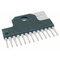
Dia 1 .079 (2.0) .095 (2.4) .548 (13.9) .607 (15.4) 13 .178 (4.5) ...