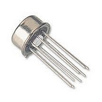
NTE941 NTE ELECTRONICS, NTE941 Datasheet - Page 2

NTE941
Manufacturer Part Number
NTE941
Description
Replacement Semiconductors FREQ COMP OP AMP
Manufacturer
NTE ELECTRONICS
Datasheet
1.NTE941.pdf
(3 pages)
Specifications of NTE941
Op Amp Type
General Purpose
No. Of Amplifiers
1
Slew Rate
0.5V/µs
Supply Voltage Range
± 5V To ± 20V
Amplifier Case Style
Metal Can
No. Of Pins
8
Operating Temperature Range
0°C To +70°C
Lead Free Status / RoHS Status
Lead free / RoHS Compliant
Lead Free Status / RoHS Status
Lead free / RoHS Compliant, Lead free / RoHS Compliant
Electrical Characteristics: (V
Input Offset Voltage
Input Offset Voltage Adjustment Range
Input Offset Current
Input Bias Current
Input Resistance
Common Mode Input Voltage Range
Large Signal Voltage Gain
Output Voltage Swing
Output Short–Circuit Current
Common–Mode Rejection Ratio
Supply Voltage Rejection Ratio
Transient Response Rise Time
Transient Response Overshoot
Transient Response Slew Rate
Supply Current
Power Consumption
Parameter
V (+)
S
= 15V, 0
Output
N.C.
7
Pin Connection Diagram
Symbol
CMRR
PSRR
V
V
t
8
V
I
6
SR
V
TLH
P
I
A
I
os
OS
I
IOR
ICR
IO
IB
r
D
IO
O
i
V
C
Offset Null
(Top View)
T
Offset Null
A
R
V
T
T
V
T
V
R
R
R
T
R
V
T
T
T
A
A
A
A
A
A
A
S
S
S
O
5
1
S
L
L
L
S
= +25 C
= +25 C
= +25 C
= +25 C
= +25 C, Unity Gain
= +25 C
= +25 C
= 20V, T
= 20V, T
= 20V to 5V, R
= 10V,
+70 C unless otherwise specified)
2k
10k
2k
10k
10k , V
Test Conditions
2
4
A
A
CM
V (–)/Case
Inverting Input
= +25 C
= +25 C
3
= 12V
T
T
Non–Inverting Input
A
A
S
= +25 C
= +25 C
10k
Min Typ Max Unit
0.3
20
15
70
77
–
–
–
–
–
–
–
–
12
10
–
–
–
–
–
–
200
2.0
2.0
0.3
0.5
1.7
20
80
25
90
96
50
–
15
–
–
12
–
14
13
5
200
300
500
6.0
7.5
0.8
2.8
85
–
–
13
–
–
–
–
–
–
–
–
–
–
V/mV
V/mV
V/ s
mW
M
mV
mV
mA
mA
nA
nA
nA
dB
dB
%
V
V
V
V
A
s


