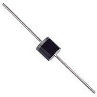
NTE571 NTE ELECTRONICS, NTE571 Datasheet

NTE571
Manufacturer Part Number
NTE571
Description
Replacement Semiconductors FAST SWITCH/SOFT REC
Manufacturer
NTE ELECTRONICS
Datasheet
1.NTE571.pdf
(1 pages)
Specifications of NTE571
Repetitive Reverse Voltage Vrrm Max
1kV
Forward Current If(av)
2.9A
Forward Voltage Vf Max
1.28V
Reverse Recovery Time Trr Max
150ns
Forward Surge Current Ifsm Max
65A
Diode Type
Soft Recovery
Lead Free Status / RoHS Status
Lead free / RoHS Compliant
Lead Free Status / RoHS Status
Lead free / RoHS Compliant, Contains lead / RoHS non-compliant
Absolute Maximum Ratings:
Repetitive Peak Reverse Voltage, V
Continuous Reverse Voltage, V
Average Forward Rectified Current, I
Repetitive Peak Forward Current, I
Non−Repetitive Peak Forward Current, I
Non−Repetitive Peak Reverse Avalanche Energy, E
Operating Junction Temperature Range, T
Storage Temperature Range, T
Thermal Resistance, Junction−to−Tie Point (10mm lead length), R
Thermal Resistance, Junction−to−Ambient, R
Electrical Characteristics: (T
Note 1. Measured under pulse conditions to avoid excessive dissipation.
Forward Voltage Drop
Reverse Avalanche Breakdown Voltage
Reverse Current
Reverse Recovery Time
T
T
t = 10ms, half sine−wave, T
I
Mounted on 1.5mm thick PC Board, Cu−thickness > 40μm
R
.394” (10mm) lead length, T
T
A
A
tp
= 400mA, T
= +65°C
= +65°C
= +55°C
Parameter
. . . . . . . . . . . . . . . . . . . . . . . . . . . . . . . . . . . . . . . . . . . . . . . . . . . . . . . . . . . . . . . . .
. . . . . . . . . . . . . . . . . . . . . . . . . . . . . . . . . . . . . . . . . . . . . . . . . . . . . . . . . . . . . . . . . .
. . . . . . . . . . . . . . . . . . . . . . . . . . . . . . . . . . . . . . . . . . . . . . . . . . . . . . . . . . . . . . . . .
J
= +175°C prior to surge; with inductive load off
.053 (1.35) Dia Max
General Purpose Silicon Rectifier
Fast Switching, Soft Recovery
stg
J
R
= +25°C unless otherwise specified)
. . . . . . . . . . . . . . . . . . . . . . . . . . . . . . . . . . . . . . . . . . . . . . . . . . .
(25.4)
1.000
Color Band Denotes Cathode
J
FRM
. . . . . . . . . . . . . . . . . . . . . . . . . . . . . . . . . . . . . . . . . .
Min
tp
RRM
= +175°C prior to surge, V
F(AV)
Symbol
= +55°C
V
(BR)R
V
I
t
FSM
R
rr
. . . . . . . . . . . . . . . . . . . . . . . . . . . . . . . . . . . . . . . . . . . . .
F
J
NTE571
. . . . . . . . . . . . . . . . . . . . . . . . . . . . . . . . . .
thja
I
I
I
V
V
when switched from
I
F
F
R
F
measured at I
. . . . . . . . . . . . . . . . . . . . . . . . . . . . . . . . . . . . . . . .
R
R
= 3A,
= 3A, Note 1
= 0.5A to I
= 0.1mA
= 1000V
= 1000V, T
RSM
Test Conditions
T
.165 (4.2) Max
J
= +175°C, Note 1
R
J
R
= 1A
= +165°C
= 0.25A
R
.169 (4.3) Max
= 1000V
thjtp
. . . . . . . . . . . . . . . . . . . . .
. . . . . . . . . . . . . . . . . . .
. . . . . . . . . . . . . . . . . .
. . . . . . . . . . . . . . . . . .
1100
Min
−
−
−
−
−
Typ Max Unit
−65° to +175°C
−65° to +175°C
−
−
−
−
−
−
1.28
1.78
150
150
−
5
Rev. 10−10
25K/W
75K/W
1000V
1000V
10mJ
2.9A
1.2A
μA
μA
ns
33A
65A
V
V
V
11A


