SV01A103AEA01B00 Murata, SV01A103AEA01B00 Datasheet - Page 11
SV01A103AEA01B00
Manufacturer Part Number
SV01A103AEA01B00
Description
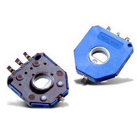
Board Mount Motion & Position Sensors 10K OHM SMD
Manufacturer
Murata
Datasheets
1.SV01A103AEA01B00.pdf
(20 pages)
2.SV01A103AEA01B00.pdf
(4 pages)
3.PVG5A201C01R00.pdf
(90 pages)
Specifications of SV01A103AEA01B00
Mounting Style
SMD/SMT
Lead Free Status / RoHS Status
Lead free / RoHS Compliant
Available stocks
Company
Part Number
Manufacturer
Quantity
Price
Company:

Part Number:
SV01A103AEA01B00
Manufacturer:
MURATA
Quantity:
250


!Note
• This PDF catalog is downloaded from the website of Murata Manufacturing co., ltd. Therefore, it’s specifications are subject to change or our products in it may be discontinued without advance notice. Please check with our
• This PDF catalog has only typical specifications because there is no space for detailed specifications. Therefore, please approve our product specifications or transact the approval sheet for product specifications before ordering.
sales representatives or product engineers before ordering.
1. Storage
(1) Storage environment
2. Board Design
<1> SMD components
!Note
• The electrodes of each SV01 series rotary position sensor
• However, if a product is exposed to high temperature and
• The following are the precautions to be observed concerning
(hereafter called "product") are plated (Au plating over Ni
plating) to ensure solderability.
humidity, sulfur gas, or other contaminated environment, the
surface of the electrodes may oxidize or sulfidize, resulting in
defective soldering.
storage management, so please refer to them.
Ensure that the atmosphere is within a temperature range of
between -10 and 40 C, and a humidity range of between 30
and 85%RH, and does not contain chlorine, sulfur, or other
corrosive gas. Also, avoid storing the products in a location
that is exposed to direct sunlight.
(1) Land pattern (use recommend land pattern only)
• Please read rating and !CAUTION (for storage, operating, rating, soldering, mounting and handling) in this catalog to prevent smoking and/or burning, etc.
• This catalog has only typical specifications because there is no space for detailed specifications. Therefore, please approve our product specifications or transact the approval sheet for product specifications before ordering.
When a land pattern area that is greater than necessary
is used, a positional error or rotation of the product may
occur due to the effect of the surface tension of the
solder, which may result in trouble when the product is
connected to a mechanical part.
Also, if the land pattern area is too small, the force
bonding the product to the printed circuit board will be
low, which may result in the product separating from the
board.
In order to prevent the above trouble, please use our
standard land pattern.
This product has two #2 terminals, at positions A and B
to ensure flexibility of mounting on the board to cope
with various wiring layouts.
This permits "in-line use" in which the #1 and #3
terminals are connected with the #2 terminal on the
same side (A), or "zigzag alignment use" in which the
#2 terminal on the B side is connected to the circuit.
In the case of "in-line use" as well, be sure to provide a
land for the #2 terminal on the B side in order to ensure
that the product is fixed to the board with adequate
force.
SV01 Series Application Manual
(2) Storage method
(3) Storage period
Store products in a condition such that the minimum packing
boxes are not subjected to a load. Do not stack the boxes to
the extent that the bottom box becomes deformed under the
weight of the boxes stacked on top of it.
Use products within 6 months after they are shipped from us.
If you use products after 6 months have elapsed, carry out a
solderability test to make sure that there is no problem prior
to use.
4-1.8
Standard Land Pattern
#1
#2
#2
5.0
Continued on the following page.
#3
B
A
(
Tolerance: 0.1
in mm
)
R51E.pdf
9
09.3.26
Related parts for SV01A103AEA01B00
Image
Part Number
Description
Manufacturer
Datasheet
Request
R

Part Number:
Description:
Murata Microblower 20x20 DCDC Driver Board - Samples Only
Manufacturer:
Murata
Part Number:
Description:
357-036-542-201 CARDEDGE 36POS DL .156 BLK LOPRO
Manufacturer:
Murata
Datasheet:
Part Number:
Description:
Manufacturer:
Murata
Datasheet:
Part Number:
Description:
Manufacturer:
Murata
Datasheet:
Part Number:
Description:
Manufacturer:
Murata
Datasheet:
Part Number:
Description:
Manufacturer:
Murata
Datasheet:
Part Number:
Description:
Manufacturer:
Murata
Datasheet:
Part Number:
Description:
Manufacturer:
Murata
Datasheet:
Part Number:
Description:
Manufacturer:
Murata
Datasheet:
Part Number:
Description:
BLM21BD751SN1On-Board Type (DC) EMI Suppression Filters
Manufacturer:
Murata
Datasheet:
Part Number:
Description:
BLM15AG100SN1On-Board Type (DC) EMI Suppression Filters
Manufacturer:
Murata
Datasheet:
Part Number:
Description:
NFE31PT222Z1E9On-Board Type (DC) EMI Suppression Filters
Manufacturer:
Murata
Datasheet:
Part Number:
Description:
Chip Coil
Manufacturer:
Murata
Datasheet:
Part Number:
Description:
Chip Coil
Manufacturer:
Murata
Datasheet: