GNM1M2R61A104MA01D Murata, GNM1M2R61A104MA01D Datasheet - Page 2
GNM1M2R61A104MA01D
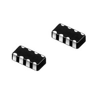
Manufacturer Part Number
GNM1M2R61A104MA01D
Description
Capacitor Arrays & Networks 0504 0.1uF 10volts X5R 20%
Manufacturer
Murata
Series
GNMr
Datasheet
1.GNM1M2R61A104MA01D.pdf
(4 pages)
Specifications of GNM1M2R61A104MA01D
Voltage Rating
10 Volts
Number Of Elements
2
Operating Temperature Range
- 55 C to + 85 C
Termination Style
SMD/SMT
Dimensions
1.37 mm L x 1 mm W x 0.2 mm H
Product
Ceramic Capacitor Arrays
Capacitance
0.1 uF
Tolerance
20 %
Temperature Coefficient
X5R
Package / Case
0504
Lead Free Status / RoHS Status
Lead free / RoHS Compliant
Available stocks
Company
Part Number
Manufacturer
Quantity
Price
Company:

Part Number:
GNM1M2R61A104MA01D
Manufacturer:
MURATA
Quantity:
640 000
Company:
Part Number:
GNM1M2R61A104MA01D
Manufacturer:
Murata Electronics North Ameri
Quantity:
40 349


No.
11
12
13
14
Continued from the preceding page.
Vibration
Resistance
Resistance to
Soldering Heat
Deflection
Solderability of
Termination
Item
Appearance
Capacitance
Q/D.F.
Appearance
Capacitance
Change
Q/D.F.
I.R.
Dielectric
Strength
No defects or abnormalities
Within the specified tolerance
30pF min. : QU1000
30pF max. :
C : Nominal
No cracking or marking defects should occur
75% of the terminations are to be soldered evenly and
continuously.
The measured and observed characteristics should satisfy the
specifications in the following table.
No marking defects
Within T2.5%
(Whichever is
larger)
30pF min. : QU1000
30pF max. :
C : Nominal
More than 10,000MΩ or 500Ω
No failure
Compensating Type
#GNMpp4
Capacitance (pF)
Capacitance (pF)
Temperature
GNM1M2
GNM212
GNM214
GNp314
QU400+20C
or T0.25pF
QU400+20C
Type
5.0
d
a
b
c
100
1.0
2.0T0.05
2.0T0.05
2.0T0.05
2.5T0.05
R7, R6 : Within T7.5%
R7, R6
R7, R6
Char.
Char.
a
Specifications
Fig. 2
0.5T0.05
0.6T0.05
0.7T0.05
0.8T0.05
25V min.
25V min.
•
0.025
0.025
max.
max.
F (Whichever is smaller)
High Dielectric Type
#GNMpp2
b
5.0
0.035
0.035
d
max.
max.
a
b
0.32T0.05
16V
16V
0.5T0.05
0.3T0.05
0.4T0.05
c
c
100
1.0
0.035
0.035
max.
max.
10V
10V
0.32T0.05
0.5T0.05
0.2T0.05
0.4T0.05
t=0.8mm
(in mm)
d
max.
max.
6.3V
0.05
6.3V
0.05
Solder the capacitor to the test jig (glass epoxy board) in the
same manner and under the same conditions as (10). The
capacitor should be subjected to a simple harmonic motion
having a total amplitude of 1.5mm, the frequency being varied
uniformly between the approximate limits of 10 and 55Hz. The
frequency range, from 10 to 55Hz and return to 10Hz, should
be traversed in approximately 1 minute. This motion should be
applied for a period of 2 hours in each 3 mutually perpendicular
directions (total of 6 hours).
Solder the capacitor on the test jig (glass epoxy board) shown
in Fig. 2 using a eutectic solder.
Then apply a force in the direction shown in Fig. 3 for 5T1 sec.
The soldering should be done either with an iron or using the
reflow method and should be conducted with care so that the
soldering is uniform and free of defects such as heat shock.
Immerse the capacitor in a solution of ethanol (JIS-K-8101) and
rosin (JIS-K-5902) (25% rosin in weight proportion). Preheat at
80 to 120°C for 10 to 30 seconds. After preheating, immerse in
eutectic solder solution for 2T0.5 seconds at 230T5°C.
Preheat the capacitor at 120 to 150°C for 1 minute. Immerse
the capacitor in a eutectic solder solution at 270T5°C for
10T0.5 seconds. Let sit at room temperature for 24T2 hours
(temperature compensating type) or 48T4 hours (high dielectric
constant type), then measure.
• Initial measurement for high dielectric constant type
Perform a heat treatment at 150+0/-10°C for one hour and
then let sit for 48T4 hours at room temperature.
Perform the initial measurement.
R230
45
Capacitance meter
Test Method
20
Fig. 3
50
Continued on the following page.
Pressurize
45
Pressurizing
speed : 1.0mm/sec.
Flexure : V1
Related parts for GNM1M2R61A104MA01D
Image
Part Number
Description
Manufacturer
Datasheet
Request
R

Part Number:
Description:
Murata Microblower 20x20 DCDC Driver Board - Samples Only
Manufacturer:
Murata
Part Number:
Description:
357-036-542-201 CARDEDGE 36POS DL .156 BLK LOPRO
Manufacturer:
Murata
Datasheet:
Part Number:
Description:
Manufacturer:
Murata
Datasheet:
Part Number:
Description:
Manufacturer:
Murata
Datasheet:
Part Number:
Description:
Manufacturer:
Murata
Datasheet:
Part Number:
Description:
Manufacturer:
Murata
Datasheet:
Part Number:
Description:
Manufacturer:
Murata
Datasheet:
Part Number:
Description:
Manufacturer:
Murata
Datasheet:
Part Number:
Description:
Manufacturer:
Murata
Datasheet:
Part Number:
Description:
BLM21BD751SN1On-Board Type (DC) EMI Suppression Filters
Manufacturer:
Murata
Datasheet:
Part Number:
Description:
BLM15AG100SN1On-Board Type (DC) EMI Suppression Filters
Manufacturer:
Murata
Datasheet:
Part Number:
Description:
NFE31PT222Z1E9On-Board Type (DC) EMI Suppression Filters
Manufacturer:
Murata
Datasheet:
Part Number:
Description:
Chip Coil
Manufacturer:
Murata
Datasheet:
Part Number:
Description:
Chip Coil
Manufacturer:
Murata
Datasheet: