SF2120C RFM, SF2120C Datasheet

Filters 149.0MHz, Orbcom TX RF SAW Filter

SF2120C

Manufacturer Part Number
SF2120C
Description
Filters 149.0MHz, Orbcom TX RF SAW Filter
Manufacturer
RFM
Datasheet

Specifications of SF2120C

Product
RF SAW Filters
Frequency
149 MHz
Operating Temperature Range
- 40 C to + 85 C
Voltage Rating
3 V
Termination Style
SMD/SMT
Lead Free Status / RoHS Status
Lead free / RoHS Compliant

Available stocks

Company
Part Number
Manufacturer
Quantity
Price
Part Number:
SF2120C
Manufacturer:
RFMD
Quantity:
5 000
Company:
Part Number:
SF2120C/NTRG
Quantity:
3 296
Electrical Connections
1.
2.
3.
4.
5.
6.
7.
www.RFM.com E-mail: info@rfm.com
©2009-2010 by RF Monolithics, Inc.
Electrical Characteristics
• Designed for Broadband Receiver IF Applications
• Low Insertion Loss
• 5.0 X 5.0 mm Surface-mount Case
• Differential Input and Single-ended Output
• Complies with Directive 2002/95/EC (RoHS)
Absolute Maximum Ratings
Port 1
Port 2
Single-ended Operation
Differential Operation
Dot indicates Pin 1
Rating
Maximum Incident Power in Passband
Maximum DC Voltage on any Non-ground Terminal
Storage Temperature Range in Tape and Reel
Suitable for Lead-free Soldering - Maximum Soldering Profile
Characteristic
Nominal Center Frequency
Insertion Loss
2 dB Bandwidth
Amplitude Ripple, 148 to 150 MHz, -27.5 to 72.5 °C
Amplitude Ripple, 148 to 150 MHz, -40 to -27.5 °C, 72.5 to 85 °C
Rejection, f
Rejection, f
Center Frequency Temperature Coefficent
Operating Temperature
Case Style
Lid Symbolization (Y=year, WW=week, S=shift)
Unless noted otherwise, all specifications apply over the operating temperature range with filter soldered to the specified demonstration board with impedance
matching to 50 Ω and measured with 50 Ω network analyzer.
Rejection is measured as attenuation below the minimum IL point in the passband. Rejection in final user application is dependent on PCB layout and external
impedance matching design. See Application Note No. 42 for details.
The design, manufacturing process, and specifications of this filter are subject to change.
Tape and Reel Standard ANSI / EIA 481.
US and international patents may apply.
RFM, stylized RFM logo, and RF Monolithics, Inc. are registered trademarks of RF Monolithics, Inc.
The center frequency will move with ambient temperature changes.
CAUTION: Electrostatic Sensitive Device. Observe precautions for handling.
Notes:
C
C
-2.5 MHz
+2.5 MHz
Differential Input
Output
Ground
Connection
Return is ground
Return is hot
Terminals
All others
Pb
1, 2
5
-40 to +85
Value
+10
3
Sym
260 °C for 30 s
f
C
148 to 150
Min
SM5050-8 5 x 5 mm Nominal Footprint
-40
15
15
Units
VDC
dBm
°C
147.65 to 150.35
RFM 635 YWWS
149.00
Typ
2.0
1.5
2.0
-30
54
30
149.00 MHz
SAW Filter
SF2120C
SM5050-8
Max
2.5
1.8
2.2
85
SF2120C - 6/14/10
Page 1 of 7
Units
ppm/K
dB
dB
MHz
MHz
dB
dB
dB
°C
P-P
P-P

Related parts for SF2120C

SF2120C Summary of contents

Page 1

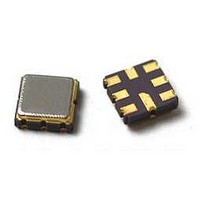
... SM5050 Nominal Footprint Terminals All others Return is ground Return is hot SF2120C 149.00 MHz SAW Filter SM5050-8 Typ Max Units 149.00 MHz 2.0 2.5 dB 147.65 to 150.35 MHz 1.5 1.8 dB P-P 2.0 2 -30 ppm/K 85 °C RFM 635 YWWS Page SF2120C - 6/14/10 ...

Page 2

... www.RFM.com E-mail: info@rfm.com ©2009-2010 by RF Monolithics, Inc. Page SF2120C - 6/14/10 ...

Page 3

... E-mail: info@rfm.com ©2009-2010 by RF Monolithics, Inc SF2120C 5pF 51nH 50 ohm Page SF2120C - 6/14/10 ...

Page 4

... CH1 S11 484 -46 . 605 149 . 000 000 MHz SF2120C DEMO # 2 FULL 2 PORTS CAL. Cor Full CENTR 149 . 000 MHz SPAN CH2 S21 LOG 10 dB/ Cor Full CENTER 149 . 000 www.RFM.com E-mail: info@rfm.com ©2009-2010 by RF Monolithics, Inc. CH3 22 . 919 445 149 . 000 ...

Page 5

... CH1 S21 DEL 200 ns/ SF2120C DEMO # 2 THRU CAL. Smo Cor Resp CH2 S21 LOG 1 dB/ Cor Resp CH2 CENTER 149 . 000 S11 401-1624-001 501-0782-470 501-0782-560 501-0621-033 www.RFM.com E-mail: info@rfm.com ©2009-2010 by RF Monolithics, Inc. 12 Jul 2007 08:52:09 REF -113 1 REF -2. 77460 1 000 ...

Page 6

... Materials 0.3 to 1.0 µm Gold over 1.27 to 8.89 µm Nickel 2.0 to 3.0 µm Nickel Al O Ceramic Free BOTTOM VIEW Max 0.205 0.205 0.067 0.086 0.050 0.028 0.106 Page SF2120C - 6/14/10 ...

Page 7

... E-mail: info@rfm.com ©2009-2010 by RF Monolithics, Inc. 12.0 2.0 COMPONENT ORIENTATION and DIMENSIONS Carrier Tape Dimensions PIN #1 “B” Nominal Size Quantity Per Reel Inches millimeters 7 178 13 330 Pitch W USER DIRECTION OF FEED 500 3000 5.3 mm 5.3 mm 2.0 mm 8.0 mm 12.0 mm Page SF2120C - 6/14/10 ...

Related keywords