D38999/26WJ35PN Amphenol, D38999/26WJ35PN Datasheet - Page 197
D38999/26WJ35PN
Manufacturer Part Number
D38999/26WJ35PN
Description
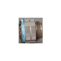
Circular MIL / Spec Connectors 128P SIZE 25 STRAIGHT PLUG PIN
Manufacturer
Amphenol
Series
38999 Seriesr
Datasheet
1.D3899926WG41SN.pdf
(208 pages)
Specifications of D38999/26WJ35PN
Mil Type
MIL-DTL-38999 III
Product Type
Connectors
Contact Style
Pin (Male)
Shell Style
Plug
Shell Size
25
Number Of Contacts
128
Insert Arrangement
25-35
Mating Style
Threaded
Mounting Style
Cable
Termination Style
Crimp
Shell Plating
Cadmium over Aluminum
Lead Free Status / RoHS Status
Lead free / RoHS Compliant


196
Amphenol
Contact Amphenol Aerospace for more information 800-678-0141 • www.amphenol-aerospace.com
HOW TO ORDER INFORMATION
For Header Assembly with MIL-DTL-38999 Connectors
Use coded number as follows:
Designates Amphenol
Header Assembly
Shell size designation for
MIL-DTL-38999 Series I,
II, III and IV see Suffix chart.
Arrangement number - See MIL-STD-1560
or MIL-STD-1669. See insert availability charts on
pages 4-7.
Contact PCB Stickout designation
See Suffix chart.
The drawing below shows the standard header assembly for use with MIL-DTL-38999 connectors.
Consult Amphenol Aerospace, Sidney NY for drawings of headers for ARINC configurations.
For how to order information on adapters to be used
with ARINC connectors, consult Amphenol, Sidney NY.
21-904008-XX( ) 8/9
21-904010-XX( ) 10/11
21-904012-XX( ) 12/13
21-904014-XX( ) 14/15
21-904016-XX( ) 16/17
21-904018-XX( ) 18/19
21-904020-XX( ) 20/21
21-904022-XX( ) 22/23
21-904024-XX( ) 24/25
Assembly Part
Series III TV
Number
Aerospace
VISUAL
INDICATOR NOTCH
FOR TOP C OF
INSERT PATTERN
(SIZE & CONFIGURATION
OPTIONAL)
† TP designates true position dimensioning.
L
See Suffix Chart
Shell
Size
Series II JT
.094
.094
.094
.125
.125
.125
.125
.125
.125
F Ra-
dius
21-9040
± .005
G
Assemblies containing Size 22 contacts only: .175
Assemblies containing Size16 or 20 contacts: .195
R1
R2
.938
1.031
1.125
1.219
1.312
1.438
1.562
1.688
1.812
S
± .005
Series I LJT
MIL-DTL-38999, Series III TV, II JT, I LJT
S
XX - XX
.128
.128
.128
.128
.128
.128
.128
.154
.154
– .006
Universal “Header Assembly” for Flex Print
.008
T +
.719
.812
.906
.969
1.062
1.156
1.250
1.375
1.500
TT
T
TP†
R1
F RADIUS
X
.594
.719
.812
.906
.969
1.062
1.156
1.250
1.375
TP†
R2
*Shell size designation for MIL-DTL-38999 Series I, II, III and IV and
** Size 22 contacts available in all 3 stickout lengths.
*** Insert arrangement 14-97 and 15-97 are not available at this time.
MIL-DTL-26482 Series 1 and 2.
Examples: Shell size 9 use 08. Shell size 25 use 24.
Shell Size
Designation*
Size 16 and 20 contacts available only in .185 and .270 lengths.
Consult Amphenol, Sidney NY for information.
.216
.194
.194
.173
.194
.194
.194
.242
.242
+ .008
– .006
TT
ASSEMBLY NUMBER SUFFIX CHART
08
10
12
14
16
18
20
22
24
or PC board connectors
Insert Arrangement
Number Suffix***
.050
MIL-STD-1560 or
MIL-STD-1669
Arrangement
NOTE:
Size 22 accepts .018 to .022 dia. PCB tails.
Size 16 accepts .048 to .064 dia. PCB tails.
Size 20 accepts .037 to .043 dia. PCB tails.
Suffix from
G
G
.020 ± .001
B
PCB STICKOUT
(SEE SUFFIX CHART BELOW)
B
PCB STICKOUT
(SEE SUFFIX CHART BELOW)
.040 ± .001 (SIZE 20)
.0625 ± .0010 (SIZE 16)
SIZE 22
CONTACT VIEW
SIZE 16 AND 20
CONTACT VIEW
Contact PCB
Stickout***
Suffix
1
2
3
B ± .015
Stickout
.120
.185
.270
Related parts for D38999/26WJ35PN
Image
Part Number
Description
Manufacturer
Datasheet
Request
R

Part Number:
Description:
Conn MIL-DTL-38999 Circular SKT 26 POS Crimp ST Cable Mount 26 Terminal 1 Port
Manufacturer:
Amphenol
Datasheet:
Part Number:
Description:
Conn MIL-DTL-38999 Circular SKT 26 POS Crimp ST Cable Mount 26 Terminal 1 Port
Manufacturer:
Amphenol
Datasheet:

Part Number:
Description:
TV 26C 26#20 SKT RECP
Manufacturer:
Amphenol Industrial Operations
Part Number:
Description:
TV 26C 26#20 SKT RECP
Manufacturer:
Amphenol Industrial Operations
Part Number:
Description:
TV 26C 26#20 SKT RECP
Manufacturer:
Amphenol Industrial Operations

Part Number:
Description:
Cable Specification: PU CABLE, UL20549 24AWG*8C+AD,OD= 6.0mm
Manufacturer:
Amphenol