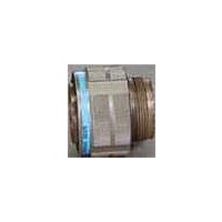
D38999/26WJ35PN Amphenol, D38999/26WJ35PN Datasheet - Page 27

D38999/26WJ35PN
Manufacturer Part Number
D38999/26WJ35PN
Description
Circular MIL / Spec Connectors 128P SIZE 25 STRAIGHT PLUG PIN
Manufacturer
Amphenol
Series
38999 Seriesr
Datasheet
1.D3899926WG41SN.pdf
(208 pages)
Specifications of D38999/26WJ35PN
Mil Type
MIL-DTL-38999 III
Product Type
Connectors
Contact Style
Pin (Male)
Shell Style
Plug
Shell Size
25
Number Of Contacts
128
Insert Arrangement
25-35
Mating Style
Threaded
Mounting Style
Cable
Termination Style
Crimp
Shell Plating
Cadmium over Aluminum
Lead Free Status / RoHS Status
Lead free / RoHS Compliant
- Current page: 27 of 208
- Download datasheet (11Mb)
26
Amphenol
Contact Amphenol Aerospace for more information at 800-678-0141 • www.amphenol-aerospace.com
Shell
Size
Shell
Size
To complete,
see how to order
pages 21-23.
11
13
15
17
19
21
23
25
PART #
Consult Amphenol Aerospace for availability of composite box mount receptacles.
All dimensions for reference only
9
11
13
15
17
19
21
23
25
†† Blue band indicates rear release contact retention system
9
† Red band indicates fully mated
Shell
Code
TT
4 PLACES
Size
MS
Shell
Code
Size
A
B
C
D
G
H
E
F
J
MS
A
B
C
D
E
G
H
F
J
2 PLACES
2 PLACES
2 PLACES
Aerospace
TS (Plated)
0.1P=0.3L-
L Max.
B Thread
Class 2A
R
R
(TV)
5.21
5.21
5.21
5.21
5.21
5.21
5.97
5.97
5.97
S
1.0000
1.1875
1.2500
1.3750
1.5000
1.6250
1
2
.6250
.7500
.8750
.005
.13
Connector
(CTV)
CTVPS
Max.
6.35
6.35
6.35
6.35
6.35
6.35
7.11
7.11
7.11
CTVP
TVPS
TVPS
TVPS
M
M
TVP
L
Type
1
L Max.
(TV)
.205
.205
.205
.205
.205
.205
.235
.235
.235
M +.00
20.83
20.83
20.83
20.83
20.83
20.83
20.07
20.07
20.07
–.13
(TV)
Shell
Style
02
02
02
02
02
02
(CTV)
Max.
.250
.250
.250
.250
.250
.250
.280
.280
.280
METAL
T
4 PLACES
L
1
19.63
19.63
19.63
19.63
19.63
19.63
18.82
18.82
18.82
Service
+.00
–.13
(TV)
Class
RW
RW
M
RK
RF
RS
RF
1
+.000
–.005
(TV)
.820
.820
.820
.820
.820
.820
.790
.790
.790
M
& Insert Arrg
18.26
20.62
23.01
24.61
26.97
29.36
31.75
34.92
38.10
Shell Size
THREAD
R
9-35
X-X
X-X
X-X
X-X
X-X
+.000
–.005
1
(TV)
.773
.773
.773
.773
.773
.773
.741
.741
.741
B
M
1
BLUE
BAND
RED
BAND
15.09
18.26
20.62
23.01
24.61
26.97
29.36
31.75
34.92
R
1.062
1.156 1.062 1.449 .128
1.250 1.156 1.575 .128
1.375 1.250 1.701 .154
1.500 1.375 1.823 .154
Contact
.719
.812
.906
.969
2
††
†
Type
R
P
X
X
X
X
X
1
M (TV)
M (CTV)
LL (TV)
LL (CTV)
Max.
43.3
46.4
24.1
26.5
28.9
31.3
33.7
36.9
40.1
1
S
AA
1
Z (TV)
Z (CTV)
Alternate
Position
.594
.719 1.043 .128
.812 1.137 .128
.906 1.232 .128
.969 1.323 .128
1
R
2
B
X
X
X
X
X
±.20
3.91
3.91
3.25
3.25
3.25
3.25
3.25
3.25
3.25
T
Max.
CTVP02R – Crimp, Composite
.948 .128
S
Variations
Special
(XXX)
(XXX)
(XXX)
(XXX)
(XXX)
(453)
Max.
(TV)
3.89
3.89
3.89
3.89
3.89
3.89
4.65
4.65
4.65
Z.
±.008
L (TV)
L (CTV)
T
1
(CTV)
Max.
5.03
5.03
5.03
5.03
5.03
5.03
5.79
5.79
5.79
Z
Max.
(TV)
.153
.153
.153
.153
.153
.153
.183
.183
.183
1
Z.
TVP02R – Crimp, Metal
A
Designates true position dimensioning
Mount
Panel
16.66
20.22
23.42
26.59
30.96
32.94
36.12
39.29
42.47
(CTV)
1
Max.
.198
.198
.198
.198
.198
.198
.228
.228
.228
Back
Box Mounting Receptacle
Z
1
Mount
Panel
1.040
1.210 1.010
1.280 1.130
1.410 1.250
1.530 1.360
1.660 1.470
Back
.650
.800
.910
Mount
Front
Panel
13.11
15.88
19.05
23.01
25.81
28.98
32.16
34.93
37.69
A
A
1
2
Mount
Panel
Front
.510
.620
.740
.900
A
Max.
5.94
5.94
5.94
5.94
5.94
5.94
5.18
5.18
5.18
2
AA
PANEL HOLE
DIMENSIONS
FRONT PANEL
BACK PANEL
MOUNTING
MOUNTING
AA Max.
Thick-
Panel
ness
.234
.234
.234
.234
.234
.234
.204
.204
.204
–.00 (TV)
LL +.15
22.99
22.99
22.99
22.99
22.99
22.99
22.99
22.99
22.99
A
A
1
2
+.006
–.000
(TV)
.905
.905
.905
.905
.905
.905
.905
.905
.905
LL
(CTV)
23.06
23.06
23.06
23.06
23.06
23.06
22.96
22.96
22.96
±.13
LL1
±.005
(CTV)
.908
.908
.908
.908
.908
.908
.904
.904
.904
LL1
Millimeters
±.20
5.49
4.93
4.93
4.39
4.93
4.93
4.93
6.15
6.15
Inches
TT
±.008
.216
.194
.194
.173
.194
.194
.194
.242
.242
TT
Related parts for D38999/26WJ35PN
Image
Part Number
Description
Manufacturer
Datasheet
Request
R

Part Number:
Description:
Conn MIL-DTL-38999 Circular SKT 26 POS Crimp ST Cable Mount 26 Terminal 1 Port
Manufacturer:
Amphenol
Datasheet:

Part Number:
Description:
Conn MIL-DTL-38999 Circular SKT 26 POS Crimp ST Cable Mount 26 Terminal 1 Port
Manufacturer:
Amphenol
Datasheet:

Part Number:
Description:
TV 26C 26#20 SKT RECP
Manufacturer:
Amphenol Industrial Operations

Part Number:
Description:
TV 26C 26#20 SKT RECP
Manufacturer:
Amphenol Industrial Operations

Part Number:
Description:
TV 26C 26#20 SKT RECP
Manufacturer:
Amphenol Industrial Operations

Part Number:
Description:
Cable Specification: PU CABLE, UL20549 24AWG*8C+AD,OD= 6.0mm
Manufacturer:
Amphenol


