E2E2-X5B1-M1 Omron, E2E2-X5B1-M1 Datasheet - Page 4
E2E2-X5B1-M1
Manufacturer Part Number
E2E2-X5B1-M1
Description
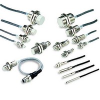
Proximity Sensors E2 WITH M12 CONNECTOR
Manufacturer
Omron
Series
E2E2r
Specifications of E2E2-X5B1-M1
Maximum Operating Temperature
+ 85 C
Supply Voltage
10 V to 55 V
Supply Current
13 mA
Operating Supply Voltage
10 V to 55 V
Mounting Style
Cable
Minimum Operating Temperature
- 40 C
Maximum Output Current
200 mA
Features
NO
Sensing Distance
5 mm
Sensor Input
Inductive
Sensing Range
5mm
Supply Voltage Range Dc
10V To 55V
Sensor Housing
Barrel
Sensing Range Max
5mm
Switch Terminals
Connector
Sensor Output
PNP, NO
Sensor Type
Inductive
Sensing Object
Metallic
Response Frequency
600Hz
Material - Body
Nickel-Plated Brass
Shielding
Shielded
Voltage - Supply
10 V ~ 55 V
Output Type
PNP-NO
Terminal Type
Connector
Package / Case
Cylinder, Threaded - M18
Lead Free Status / RoHS Status
Lead free / RoHS Compliant
Lead Free Status / RoHS Status
Lead free / RoHS Compliant, Lead free / RoHS Compliant


E2E2-X@Y@ AC 2-Wire Models
*1. When supplying 24 VAC to any of the above models, make sure that the operating ambient temperature range is at least −25°C to 85°C.
*2. When using an M18 or M30 Connector Model at an ambient temperature between 70 and 85°C, make sure that the Sensor has a control output (load current) of 5
Item
Sensing distance
Set distance
Differential travel
Sensing object
Standard sensing object
Response frequency
Power supply voltage (op-
erating voltage range) *1
Leakage current
Control
output
Indicators
Operation mode
(with sensing object ap-
proaching)
Ambient temperature *1, 2
Ambient humidity
Temperature influence
Voltage influence
Insulation resistance
Dielectric strength
Vibration resistance
(destruction)
Shock resistance
(destruction)
Degree of protection
Connection method
Weight (packed state)
Materi-
als
Accessories
to 200 mA max.
Load current *2
Residual voltage Refer to Engineering Data on page 5.
Case
Sensing surface PBT
Clamping nuts
Toothed washer Zinc-plated iron
Shielding
Model
Size
2 mm±10%
0 to 1.6 mm
10% max. of sensing distance
Ferrous metal (The sensing distance decreases with non-ferrous metal. Refer to Engineering Data on
page 5.)
Iron,
12 × 12 × 1 mm
25 Hz
24 to 240 VAC (20 to 264 VAC), 50/60 Hz
1.7 mA max.
5 to 200 mA
Operation indicator (red)
Y1 Models: NO
Y2 Models: NC
Operating/Storage: −40 to 85°C (with no icing or condensation)
Operating/Storage: 35% to 95% (with no condensation)
±15% max. of sensing distance at 23°C in the temperature range of −40 to 85°C,
±10% max. of sensing distance at 23°C in the temperature range of −25 to 70°C
±1% max. of sensing distance at rated voltage in the rated voltage ±15% range
50 MΩ min. (at 500 VDC) between current-carrying parts and case
4,000 VAC, 50/60 Hz for 1 minute between current carry parts and case
10 to 55 Hz, 1.5-mm double amplitude for 2 hours each in X, Y, and Z directions
1,000 m/s
IEC IP67, in-house standard for oil resistance
Pre-wired Models (Standard cable length: 2 m) and Connector Models
Approx. 65 g
Brass
Nickel-plated brass
Instruction sheet
E2E2-X2Y@
Shielded
2
10 times each in X, Y, and Z directions
M12
Refer to the timing charts under I/O Circuit Diagrams on page 8 for details.
5 mm±10%
0 to 4 mm
Iron,
15 × 15 × 1 mm
E2E2-X5MY@
Unshielded
5 mm±10%
0 to 4 mm
Iron,
18 × 18 × 1 mm
5 to 300 mA
Approx. 150 g
E2E2-X5Y@
Shielded
M18
10 mm±10%
0 to 8 mm
Iron,
30 × 30 × 1 mm
E2E2-X10MY@
Unshielded
10 mm±10%
0 to 8 mm
Iron,
30 × 30 × 1 mm
Approx. 210 g
E2E2-X10Y@
Shielded
M30
18 mm±10%
0 to 14 mm
Iron,
54 × 54 × 1 mm
E2E2-X18MY@
Unshielded
E2E2
4
Related parts for E2E2-X5B1-M1
Image
Part Number
Description
Manufacturer
Datasheet
Request
R

Part Number:
Description:
E2E2-X5MB1 W/ M12 CONNECTOR
Manufacturer:
Omron
Datasheet:

Part Number:
Description:
PROX LONG M30, 10mm NPN-NC 2M
Manufacturer:
Omron
Datasheet:
Part Number:
Description:
PROX LONG M18, 10mm PNP-NO 2M
Manufacturer:
Omron
Datasheet:
Part Number:
Description:
PROX LONG M18,10mm NPN-NO 2M
Manufacturer:
Omron
Datasheet:

Part Number:
Description:
PROX LONG M30,10mm AC2W-NO(COO
Manufacturer:
Omron
Datasheet:
Part Number:
Description:
PROX LONG M12,2mm NPN-NC 2M
Manufacturer:
Omron
Datasheet:
Part Number:
Description:
PROX LONG M12,2mm AC2W-NC 2M
Manufacturer:
Omron
Datasheet:
Part Number:
Description:
PROX LONG M18,5mm NPN-NC 2M
Manufacturer:
Omron
Datasheet: