PKU4513PI Ericsson Power Modules, PKU4513PI Datasheet - Page 17
PKU4513PI
Manufacturer Part Number
PKU4513PI
Description
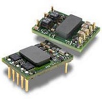
DC/DC Converters & Regulators 12Vdc 4.2A Isolated Input 36-75V 50W
Manufacturer
Ericsson Power Modules
Series
PKUr
Datasheet
1.PKU4513PI.pdf
(38 pages)
Specifications of PKU4513PI
Output Power
50 W
Input Voltage Range
36 V to 75 V
Number Of Outputs
1
Output Voltage (channel 1)
12 V
Output Current (channel 1)
4.2 A
Isolation Voltage
1.5 KV
Package / Case Size
Sixteenth Brick
Output Type
Isolated
Product
Isolated
Lead Free Status / RoHS Status
Lead free / RoHS Compliant
Available stocks
Company
Part Number
Manufacturer
Quantity
Price
Company:

Part Number:
PKU4513PI
Manufacturer:
ERICSSON
Quantity:
12 000


3.3 V/15 A Electrical Specification
T
Typical values given at: T
An external capacitor of 1
Characteristics
V
V
V
C
P
η
P
P
P
f
V
V
V
t
t
t
t
t
I
I
I
V
OVP
Note 1: See Operating Instruction, section Turn-off Input Voltage
Note 2: V
Note 3: RMS current in hiccup mode, V
Prepared (also subject responsible if other)
EQUENXU
Approved
SEC/D (Julia You)
PKU 4000 Series
DC/DC converters, Input 36-75 V, Output 25 A/50 W
s
tr
r
s
f
RC
O
lim
sc
ref
I
Ioff
Ion
O
d
li
RC
Oi
O
tr
Oac
I
= -30 to +110ºC, V
I
min 38 V to obtain 3.63 V at 49.5 W output power.
Input voltage range
Turn-off input voltage
Turn-on input voltage
Internal input capacitance
Output power
Efficiency
Power Dissipation
Input idling power
Input standby power
Switching frequency
Output voltage initial setting and
accuracy
Output adjust range
Output voltage tolerance band
Idling voltage
Line regulation
Load regulation
Load transient
voltage deviation
Load transient recovery time
Ramp-up time
(from 10−90 % of V
Start-up time
(from V
V
(from V
RC start-up time
RC shut-down fall time
(from RC off to 10 % of V
Output current
Current limit threshold
Short circuit current
Output ripple & noise
Over voltage protection
I
shut-down fall time
I
I
off to 10 % of V
connection to 90 % of V
I
= 36 to 75 V, sense pins connected to output pins unless otherwise specified under Conditions.
ref
µ
Oi
= +25°C, V
F is used on the input during all measurements.
)
O
O
lower than aprox 0.5 V.
)
O
)
Oi
I
= 53 V, max I
)
Conditions
Decreasing input voltage,
see Note 1
Increasing input voltage
see Note 1
Output voltage initial setting
50 % of max I
max I
50 % of max I
max I
max I
I
V
0-100 % of max I
T
See operating information and note 2
0-100 % of max I
I
max I
V
V
max I
0-100 % of max I
max I
I
max I
max I
I
T
T
See ripple & noise section,
max I
T
max I
O
O
O
O
I
ref
I
I
ref
ref
ref
= 0 A, V
= 53 V, Load step 25-75-25 % of
= 0 A
= 10 % of max I
= 10 % of max I
= 53 V (turned off with RC)
= 53 V, 0-100 % of max I
= +25°C, V
< max T
= 25ºC, see Note 3
= +25°C, V
O
O
O
O
O
O
O
O
O
O
, di/dt = 1 A/
, V
, V
O
Oi
, unless otherwise specified under Conditions.
I
I
Checked
EJUNGYA
= 48 V
= 53 V
ref
O
O
I
I
= 53 V, 0-100 % of
= 53 V, max I
, V
O
O
O
I
O
O
µ
= 48 V
s.
O
PRODUCT SPECIFICATION
No.
2/1301-BMR 602 4510/1 Uen
Date
2008-06-26
O
3.24
1.90
3.20
3.24
min
290
2.5
0.1
1.0
36
29
32
16
0
6
0
Technical Specifi cation
EN/LZT 146 308 R4B July 2008
© Ericsson Power Modules AB
Rev
PF1
-165/+150
89.7
89.2
89.9
89.3
0.15
3.30
4.35
320
typ
0.5
6.0
1.8
0.2
1.4
1.5
31
33
20
18
14
60
1
8
4
8
6
1
Reference
-330/+250
Max
34.5
49.5
3.36
3.63
3.40
3.36
350
100
9.5
4.6
0.3
1.6
75
33
10
18
40
15
22
9
PKU 4510 PI
mVp-p
Unit
kHz
mV
mV
mV
ms
ms
ms
ms
ms
ms
m
µ
%
µs
W
W
W
W
V
V
V
V
V
V
V
A
A
A
V
2 (5)
F
17
s
Related parts for PKU4513PI
Image
Part Number
Description
Manufacturer
Datasheet
Request
R

Part Number:
Description:
DC/DC Converters & Regulators 33W 12V OUT 2.75A 33.02x22.86x7.50 mm
Manufacturer:
Ericsson Power Modules
Datasheet:
Part Number:
Description:
DC/DC Converters & Regulators 34W 15V OUT 2.25A 33.02x22.86x7.50 mm
Manufacturer:
Ericsson Power Modules
Datasheet:
Part Number:
Description:
DC/DC Converters & Regulators 34W 15V OUT 2.25A 33.02x22.86x7.50 mm
Manufacturer:
Ericsson Power Modules
Datasheet:
Part Number:
Description:
DC/DC Converters & Regulators 33W 12V OUT 2.75A 33.02x22.86x7.50 mm
Manufacturer:
Ericsson Power Modules
Datasheet:
Part Number:
Description:
DC/DC Converters & Regulators 35W 7V OUT 7A 33.02x22.86x7.50 mm
Manufacturer:
Ericsson Power Modules
Datasheet:
Part Number:
Description:
DC/DC Converters & Regulators 33W 3.3V OUT 10A 33.02x22.86x7.50 mm
Manufacturer:
Ericsson Power Modules
Datasheet:

Part Number:
Description:
DC/DC Converters & Regulators 100W 5V OUT 20A 27.9x22.8x8.3 mm
Manufacturer:
Ericsson Power Modules
Part Number:
Description:
DC/DC Converters & Regulators 100W 5V OUT 20A 27.9x22.8x8.3 mm
Manufacturer:
Ericsson Power Modules
Part Number:
Description:
DC/DC Converters & Regulators 120W 12V OUT 10A 27.9x22.8x8.3 mm
Manufacturer:
Ericsson Power Modules
Part Number:
Description:
DC/DC Converters & Regulators 120W 12V OUT 10A 27.9x22.8x8.3 mm
Manufacturer:
Ericsson Power Modules
Part Number:
Description:
Module DC-DC 1-OUT 5V 20A 100W Quarter-Brick
Manufacturer:
Ericsson Power Modules

Part Number:
Description:
Module DC-DC 1-OUT 12V 6A 72W 8-Pin 1/8-Brick
Manufacturer:
Ericsson Power Modules
Datasheet:
Part Number:
Description:
Manufacturer:
Ericsson Power Modules
Datasheet:
Part Number:
Description:
Module DC-DC 1-OUT 12V 1A 12W 18-Pin
Manufacturer:
Ericsson Power Modules
Datasheet:
Part Number:
Description:
Module DC-DC 2-OUT 12V/-12V 0.25A 6W 18-Pin SMD
Manufacturer:
Ericsson Power Modules