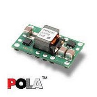
PMF8118TP Ericsson Power Modules, PMF8118TP Datasheet - Page 40

PMF8118TP
Manufacturer Part Number
PMF8118TP
Description
DC/DC Converters & Regulators 0.8-1.8V 10A Non-Iso Input 12V 18W
Manufacturer
Ericsson Power Modules
Series
PMFr
Datasheet
1.PMF8118TSR.pdf
(47 pages)
Specifications of PMF8118TP
Output Power
18 W
Input Voltage Range
10.8 V to 13.2 V
Number Of Outputs
1
Output Voltage (channel 1)
0.8 V to 1.8 V
Output Current (channel 1)
10 A
Package / Case Size
DIP
Output Type
POLA Non-Isolated Regulator
Product
Non-Isolated / POL
Lead Free Status / RoHS Status
Lead free / RoHS Compliant
Available stocks
Company
Part Number
Manufacturer
Quantity
Price
Company:
Part Number:
PMF8118TP
Manufacturer:
VICOR
Quantity:
12 000
Part Number:
PMF8118TP
Manufacturer:
ERICSSON/爱立信
Quantity:
20 000
Soft-start Power Up
From the moment a valid input voltage is applied, the soft-
start control introduces a short time-delay (typically 5-10 ms)
before allowing the output voltage to rise.
The initial rise in input current when the input voltage first
starts to rise is the charge current drawn by the input
capacitors. Power-up is complete within 15 ms.
Auto-Track™ Function
Auto-Track was designed to simplify the amount of circuitry
required to make the output vltage from each module power
up and power down in sequence. The sequencing of two or
more supply voltages during power up is a common
requirement for complex mixed-signal applications, that use
dual-voltage VLSI ICs such as DSPs, micro-processors and
ASICs.
Margin Up/Down controls
These controls allow the input voltage to be momentarily
adjusted, either up or down, by a nominal 5 %. This provides
a convenient method for dynamically testing the operation of
the load circuit over its supply margin or range. It can also be
used to verify the function of supply voltage supervisors.
Pre-Bias Startup Capability
This often occurs in complex digital systems when current
from another power source is backfed through a dual-supply
logic component, such as FPGA or ASIC.
The PMF(3.3/5.0V Vin) incorporate synchronous rectifiers, but
will not sink current during startup, or whenever the Inhibit pin
is held low. However, to ensure satisfactory operation of this
function, certain conditions must be maintained.
Prepared (also subject responsible if other)
SEC/D KEVIN YAN
Approved
SEC/D (Wei Zhang A)
PMF 8000 series
PMF 8000 series
PMF 8000 series
POL regulator, Input 10.8-13.2 V, Output 10 A/55 W
POL regulator, Input 10.8-13.2 V, Output 10 A/55 W
POL regulator, Input 10.8-13.2 V, Output 10 A/55 W
Checked
See Design Note 019 for further information.
Thermal Consideration
General
The regulators are designed to operate in different thermal
environments and sufficient cooling must be provided to
ensure reliable operation.
Cooling is achieved mainly by conduction, from the pins to
the host board, and convection, which is dependant on the
airflow across the regulator. Increased airflow enhances the
cooling of the regulator.
The Output Current Derating graph found in the Output
section for each model provides the available output current
vs. ambient air temperature and air velocity at V
The DC/DC regulator is tested on a 254 x 254 mm,
35 μm (1 oz), 8-layer test board mounted vertically in a wind
tunnel with a cross-section of 305 x 305 mm.
Proper cooling of the DC/DC regulator can be verified by
measuring the temperature at positions P1, P2 and P3. The
temperature at these positions should not exceed the max
values provided in the table below.
Note that the max value is the absolute maximum rating
(non destruction) and that the electrical Output data is
guaranteed up to T
PRODUCT SPEC.
No.
3/1301-BMR 643 8 Uen
Date
2006-02-08
Position
P
P
P
1
2
3
Device
Pcb
Mosfet
Inductor
Technical Specifi cation
Technical Specifi cation
Technical Specifi cation
EN/LZT 146 318 R1B February 2006
EN/LZT 146 318 R1B April 2006
EN/LZT 146 318 R1C Sep 2006
© Ericsson Power Modules AB
© Ericsson Power Modules AB
© Ericsson Power Modules AB
Rev
A
ref
+85°C.
Designation
T
ref
Reference
max value
130º C(L)/ 120º C (T)
130º C(L&T)
130º C(L&T)
in
= 12 V.
3 (5)
40


