GRM155R60J105KE19D Murata, GRM155R60J105KE19D Datasheet - Page 149
GRM155R60J105KE19D
Manufacturer Part Number
GRM155R60J105KE19D
Description
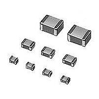
Multilayer Ceramic Capacitors (MLCC) - SMD/SMT 0402 1uF 6.3volts X5R 10%
Manufacturer
Murata
Series
GRMr
Datasheet
1.GNM1M2R61A105ME14D.pdf
(221 pages)
Specifications of GRM155R60J105KE19D
Voltage Rating
6.3 Volts
Operating Temperature Range
- 55 C to + 85 C
Temperature Coefficient / Code
X5R
Product
General Type MLCCs
Dimensions
0.5 mm W x 1 mm L x 0.5 mm H
Termination Style
SMD/SMT
Capacitance
1 uF
Tolerance
10 %
Package / Case
0402 (1005 metric)
Lead Free Status / RoHS Status
Lead free / RoHS Compliant
Available stocks
Company
Part Number
Manufacturer
Quantity
Price
Company:

Part Number:
GRM155R60J105KE19D
Manufacturer:
MURATA
Quantity:
600 000
Part Number:
GRM155R60J105KE19D
Manufacturer:
MURATA/村田
Quantity:
20 000
Part Number:
GRM155R60J105KE19D 0402 X5R 105K 6.3V
Manufacturer:
MURATA/村田
Quantity:
20 000


!Note
• This PDF catalog is downloaded from the website of Murata Manufacturing co., ltd. Therefore, it’s specifications are subject to change or our products in it may be discontinued without advance notice. Please check with our
• This PDF catalog has only typical specifications because there is no space for detailed specifications. Therefore, please approve our product specifications or transact the approval sheet for product specifications before ordering.
sales representatives or product engineers before ordering.
!Note
Table 3 GNM, LLA Series for Reflow Soldering Land Dimensions
Table 4 LLM Series for Reflow Soldering Land Dimensions
2. Adhesive Application
1. Thin or insufficient adhesive can cause the chips to
2. Low viscosity adhesive can cause chips to slip after
3. Adhesive Coverage
Notice
GNMpp2
LLM
loosen or become disconnected during flow soldering.
The amount of adhesive must be more than dimension c,
shown in the drawing at right, to obtain the correct
bonding strength.
The chip's electrode thickness and land thickness must
also be taken into consideration.
mounting. The adhesive must have a viscosity of
5000Pa
Continued from the preceding page.
GRM18, GQM18
GRM21, LLL21, GQM21
GRM31, LLL31
• Please read rating and !CAUTION (for storage, operating, rating, soldering, mounting and handling) in this catalog to prevent smoking and/or burning, etc.
• This catalog has only typical specifications because there is no space for detailed specifications. Therefore, please approve our product specifications or transact the approval sheet for product specifications before ordering.
Part Number
Part Number
Part Number
•
GNM0M2
GNM1M2
s (500ps) min. (at 25 C).
GNM212
GNM214
GNM314
e
LLM21
LLM31
LLA18
LLA21
LLA31
a
Chip Capacitor
c
p
Chip Capacitor
p
d
f
0.6 to 0.8
Adhesive Coverage*
Land
1.0
c
1.37
a
0.9
2.0
2.0
3.2
1.6
2.0
3.2
L
0.05mg min.
0.15mg min.
0.1mg min.
b'
a
b
b
b=(c-e)/2, b'=(d-f)/2
c'
*Nominal Value
(0.3 to 0.5)
(0.3 to 0.5)
b, b'
1.25
1.25
1.25
0.6
1.0
1.6
0.8
1.6
W
c, c'
0.3
0.4
0.12 to 0.20*
0.4 to 0.5
0.6 to 0.7
0.6 to 0.7
0.8 to 1.0
0.3 to 0.4
0.5 to 0.7
0.7 to 0.9
GNMpp4
LLA
a
Dimensions (mm)
Dimensions (mm)
* 0.82Va+2bV1.00
2.0 to 2.6
3.2 to 3.6
Board
d
0.35 to 0.40*
0.35 to 0.45
0.25 to 0.35
0.35 to 0.6
0.5 to 0.7
0.5 to 0.7
0.7 to 0.9
0.4 to 0.7
b
c
1.3 to 1.8
1.6 to 2.0
Chip Capacitor
Chip Capacitor
e
Land
p
Adhesive
0.25 to 0.35
0.15 to 0.25
0.3 to 0.35
0.4 to 0.5
0.3 to 0.4
0.2 to 0.3
0.3 to 0.4
Continued on the following page.
0.3
1.4 to 1.6
c
Land
2.6
f
a=20 to 70 m
b=30 to 35 m
c=50 to 105 m
a
b
a
b
Notice
0.45
0.64
1.0
0.5
0.8
0.4
0.5
0.8
c
p
0.5
0.8
p
147
C02E.pdf
10.12.20
Related parts for GRM155R60J105KE19D
Image
Part Number
Description
Manufacturer
Datasheet
Request
R

Part Number:
Description:
Murata Microblower 20x20 DCDC Driver Board - Samples Only
Manufacturer:
Murata
Part Number:
Description:
357-036-542-201 CARDEDGE 36POS DL .156 BLK LOPRO
Manufacturer:
Murata
Datasheet:
Part Number:
Description:
Manufacturer:
Murata
Datasheet:
Part Number:
Description:
Manufacturer:
Murata
Datasheet:
Part Number:
Description:
Manufacturer:
Murata
Datasheet:
Part Number:
Description:
Manufacturer:
Murata
Datasheet:
Part Number:
Description:
Manufacturer:
Murata
Datasheet:
Part Number:
Description:
Manufacturer:
Murata
Datasheet:
Part Number:
Description:
Manufacturer:
Murata
Datasheet:
Part Number:
Description:
BLM21BD751SN1On-Board Type (DC) EMI Suppression Filters
Manufacturer:
Murata
Datasheet:
Part Number:
Description:
BLM15AG100SN1On-Board Type (DC) EMI Suppression Filters
Manufacturer:
Murata
Datasheet:
Part Number:
Description:
NFE31PT222Z1E9On-Board Type (DC) EMI Suppression Filters
Manufacturer:
Murata
Datasheet:
Part Number:
Description:
Chip Coil
Manufacturer:
Murata
Datasheet:
Part Number:
Description:
Chip Coil
Manufacturer:
Murata
Datasheet: