GRM155R60J105KE19D Murata, GRM155R60J105KE19D Datasheet - Page 151
GRM155R60J105KE19D
Manufacturer Part Number
GRM155R60J105KE19D
Description
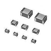
Multilayer Ceramic Capacitors (MLCC) - SMD/SMT 0402 1uF 6.3volts X5R 10%
Manufacturer
Murata
Series
GRMr
Datasheet
1.GNM1M2R61A105ME14D.pdf
(221 pages)
Specifications of GRM155R60J105KE19D
Voltage Rating
6.3 Volts
Operating Temperature Range
- 55 C to + 85 C
Temperature Coefficient / Code
X5R
Product
General Type MLCCs
Dimensions
0.5 mm W x 1 mm L x 0.5 mm H
Termination Style
SMD/SMT
Capacitance
1 uF
Tolerance
10 %
Package / Case
0402 (1005 metric)
Lead Free Status / RoHS Status
Lead free / RoHS Compliant
Available stocks
Company
Part Number
Manufacturer
Quantity
Price
Company:

Part Number:
GRM155R60J105KE19D
Manufacturer:
MURATA
Quantity:
600 000
Part Number:
GRM155R60J105KE19D
Manufacturer:
MURATA/村田
Quantity:
20 000
Part Number:
GRM155R60J105KE19D 0402 X5R 105K 6.3V
Manufacturer:
MURATA/村田
Quantity:
20 000


!Note
• This PDF catalog is downloaded from the website of Murata Manufacturing co., ltd. Therefore, it’s specifications are subject to change or our products in it may be discontinued without advance notice. Please check with our
• This PDF catalog has only typical specifications because there is no space for detailed specifications. Therefore, please approve our product specifications or transact the approval sheet for product specifications before ordering.
sales representatives or product engineers before ordering.
!Note
7. Coating
1. A crack may be caused in the capacitor due to the stress
8. Die Bonding/Wire Bonding (GMA or GMD Series)
1. Die Bonding of Capacitors
Notice
of the thermal contraction of the resin during curing
process.
The stress is affected by the amount of resin and curing
contraction.
Select a resin with small curing contraction.
The difference in the thermal expansion coefficient
between a coating resin or a molding resin and the
capacitor may cause the destruction and deterioration of
the capacitor such as a crack or peeling, and lead to the
deterioration of insulation resistance or dielectric
breakdown.
• Use the following materials for the Brazing alloys:
• Mounting
Continued from the preceding page.
Au-Sn (80/20) 300 to 320 C in N
(1) Control the temperature of the substrate so it
(2) Place the brazing alloy on the substrate and place
• Please read rating and !CAUTION (for storage, operating, rating, soldering, mounting and handling) in this catalog to prevent smoking and/or burning, etc.
• This catalog has only typical specifications because there is no space for detailed specifications. Therefore, please approve our product specifications or transact the approval sheet for product specifications before ordering.
matches the temperature of the brazing alloy.
the capacitor on the alloy. Hold the capacitor and
gently apply the load. Be sure to complete the
operation within 1 minute.
2
atmosphere
2. Select a resin that is less hygroscopic.
2. Wire Bonding
Select a resin for which the thermal expansion coefficient
is as close to that of capacitor as possible.
A silicone resin can be used as an under-coating to buffer
against the stress.
Using hygroscopic resins under high humidity conditions
may cause the deterioration of the insulation resistance of
a capacitor.
An epoxy resin can be used as a less hygroscopic resin.
• Wire
• Bonding
Gold wire: 25 micro m (0.001 inch) diameter
(1) Thermo compression, ultrasonic ball bonding.
(2) Required stage temperature: 150 to 200 C
(3) Required wedge or capillary weight: 0.2N to 0.5N
(4) Bond the capacitor and base substrate or other
devices with gold wire.
Notice
149
C02E.pdf
10.12.20
Related parts for GRM155R60J105KE19D
Image
Part Number
Description
Manufacturer
Datasheet
Request
R

Part Number:
Description:
Murata Microblower 20x20 DCDC Driver Board - Samples Only
Manufacturer:
Murata
Part Number:
Description:
357-036-542-201 CARDEDGE 36POS DL .156 BLK LOPRO
Manufacturer:
Murata
Datasheet:
Part Number:
Description:
Manufacturer:
Murata
Datasheet:
Part Number:
Description:
Manufacturer:
Murata
Datasheet:
Part Number:
Description:
Manufacturer:
Murata
Datasheet:
Part Number:
Description:
Manufacturer:
Murata
Datasheet:
Part Number:
Description:
Manufacturer:
Murata
Datasheet:
Part Number:
Description:
Manufacturer:
Murata
Datasheet:
Part Number:
Description:
Manufacturer:
Murata
Datasheet:
Part Number:
Description:
BLM21BD751SN1On-Board Type (DC) EMI Suppression Filters
Manufacturer:
Murata
Datasheet:
Part Number:
Description:
BLM15AG100SN1On-Board Type (DC) EMI Suppression Filters
Manufacturer:
Murata
Datasheet:
Part Number:
Description:
NFE31PT222Z1E9On-Board Type (DC) EMI Suppression Filters
Manufacturer:
Murata
Datasheet:
Part Number:
Description:
Chip Coil
Manufacturer:
Murata
Datasheet:
Part Number:
Description:
Chip Coil
Manufacturer:
Murata
Datasheet: