GRM1885C1H100JA01D Murata, GRM1885C1H100JA01D Datasheet - Page 132
GRM1885C1H100JA01D
Manufacturer Part Number
GRM1885C1H100JA01D
Description
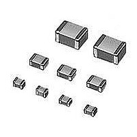
Multilayer Ceramic Capacitors (MLCC) - SMD/SMT 0603 10pF 50volts C0G 5%
Manufacturer
Murata
Series
GRMr
Datasheet
1.GNM1M2R61A105ME14D.pdf
(221 pages)
Specifications of GRM1885C1H100JA01D
Voltage Rating
50 Volts
Operating Temperature Range
- 55 C to + 125 C
Temperature Coefficient / Code
C0G (NP0)
Product
General Type MLCCs
Dimensions
0.8 mm W x 1.6 mm L x 0.8 mm H
Termination Style
SMD/SMT
Capacitance
10 pF
Tolerance
5 %
Package / Case
0603 (1608 metric)
Dielectric Characteristic
C0G / NP0
Capacitance Tolerance
± 5%
Capacitor Case Style
0603
No. Of Pins
2
Capacitor Mounting
SMD
Rohs Compliant
Yes
Lead Free Status / RoHS Status
Lead free / RoHS Compliant
Available stocks
Company
Part Number
Manufacturer
Quantity
Price
Company:

Part Number:
GRM1885C1H100JA01D
Manufacturer:
MURATA
Quantity:
640 000
Part Number:
GRM1885C1H100JA01D 0603 NPO 10PJ 50V
Manufacturer:
MURATA/村田
Quantity:
20 000


!Note
• This PDF catalog is downloaded from the website of Murata Manufacturing co., ltd. Therefore, it’s specifications are subject to change or our products in it may be discontinued without advance notice. Please check with our
• This PDF catalog has only typical specifications because there is no space for detailed specifications. Therefore, please approve our product specifications or transact the approval sheet for product specifications before ordering.
sales representatives or product engineers before ordering.
!Note
(3) Dimensions of Embossed Tape
(4) Taping Method
130
Package
q Tapes for capacitors are wound clockwise. The
w Part of the leader and part of the empty tape should be
e The top tape and base tape are not attached at the
r Missing capacitors number within 0.1% of the number
t The top tape and bottom tape should not protrude
y Cumulative tolerance of sprocket holes, 10 pitches:
u Peeling off force: 0.1 to 0.6N* in the direction shown
Continued from the preceding page.
• Please read rating and !CAUTION (for storage, operating, rating, soldering, mounting and handling) in this catalog to prevent smoking and/or burning, etc.
• This catalog has only typical specifications because there is no space for detailed specifications. Therefore, please approve our product specifications or transact the approval sheet for product specifications before ordering.
sprocket holes are to the right as the tape is pulled
toward the user.
attached to the end of the tape as follows.
end of the tape for a minimum of 5 pitches.
per reel or 1 pc, whichever is greater, and are not
continuous.
beyond the edges of the tape and should not cover
sprocket holes.
at right.
0.3mm.
GRM02
GRM43
GRM55
Part Number
Part Number
8.0 0.1
A
ø0.8 0.04
1.0 0.02
12mm width, 8mm pitch Tape
4mm width, 1mm pitch Tape
Direction of feed
*GRM02
2.0 0.1
GRM03
GMD03
GJM03
A
2.0 0.04
4.0 0.1
}
1.0 0.02
: 0.05 to 0.5N
0.23
3.6
5.2
A*
A*
ø1.5
1.75 0.1
+0.1
-0
2.5 max.
for GRM43/55
(3.7 max. for T=2.5mm)
(4.7 max. for TU3.0mm)
0.3 0.1
*Nominal Value
*Nominal Value
0.43
0.15 to 0.4
4.9
6.1
B*
B*
0.5 max.
LLL18, LLR18
LLA18
GRM21
(TU1.0mm)
LLL21
LLA21, LLM21
GRM31
(TU1.15mm)
LLL31
LLA31, LLM31
GNM31
(TU1.0mm)
GRM32
(TU1.0mm)
GQM22
Part Number
4.0 0.1
Vacant Section Chip-mounting Unit Vacant Section
160 min.
8mm width, 4mm pitch Tape
ø1.5
Direction of feed
+0.1
-0
A
Direction of Feed
4.0 0.1
2.0 0.1
1.05 0.1
1.45 0.2
1.9 0.2
2.8 0.2
2.8*
A
1.75 0.1
Continued on the following page.
190 min.
2.5 max.
(3.0 max. for T=1.8/2.0mm)
(3.7 max. for TU2.5mm)
0.2 0.1 (LLp)
0.25 0.1 (TV2.0mm)
0.3 0.1 (T=2.5mm)
*Nominal Value
1.85 0.1
2.25 0.2
3.5 0.2
3.5 0.2
Top Tape
3.5*
Base Tape
B
(Top Tape alone)
Leader unit
210 min.
(in mm)
(in mm)
C02E.pdf
10.12.20
Related parts for GRM1885C1H100JA01D
Image
Part Number
Description
Manufacturer
Datasheet
Request
R

Part Number:
Description:
Murata Microblower 20x20 DCDC Driver Board - Samples Only
Manufacturer:
Murata
Part Number:
Description:
357-036-542-201 CARDEDGE 36POS DL .156 BLK LOPRO
Manufacturer:
Murata
Datasheet:
Part Number:
Description:
Manufacturer:
Murata
Datasheet:
Part Number:
Description:
Manufacturer:
Murata
Datasheet:
Part Number:
Description:
Manufacturer:
Murata
Datasheet:
Part Number:
Description:
Manufacturer:
Murata
Datasheet:
Part Number:
Description:
Manufacturer:
Murata
Datasheet:
Part Number:
Description:
Manufacturer:
Murata
Datasheet:
Part Number:
Description:
Manufacturer:
Murata
Datasheet:
Part Number:
Description:
BLM21BD751SN1On-Board Type (DC) EMI Suppression Filters
Manufacturer:
Murata
Datasheet:
Part Number:
Description:
BLM15AG100SN1On-Board Type (DC) EMI Suppression Filters
Manufacturer:
Murata
Datasheet:
Part Number:
Description:
NFE31PT222Z1E9On-Board Type (DC) EMI Suppression Filters
Manufacturer:
Murata
Datasheet:
Part Number:
Description:
Chip Coil
Manufacturer:
Murata
Datasheet:
Part Number:
Description:
Chip Coil
Manufacturer:
Murata
Datasheet: