ADM3491ARUZ-1 Analog Devices Inc, ADM3491ARUZ-1 Datasheet - Page 8
ADM3491ARUZ-1
Manufacturer Part Number
ADM3491ARUZ-1
Description
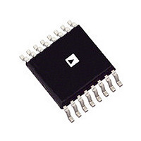
IC RS422/RS485 TXRX 250KBPS 3.6V SOIC-14
Manufacturer
Analog Devices Inc
Type
Transceiverr
Datasheet
1.ADM3491ARUZ-1.pdf
(20 pages)
Specifications of ADM3491ARUZ-1
Device Type
Differential Line Transceiver
Ic Interface Type
RS422, RS485
No. Of Drivers
1
Supply Voltage Range
3V To 3.6V
Msl
MSL 1 - Unlimited
No. Of Driver/receivers
1/1
Number Of Drivers/receivers
1/1
Protocol
RS422, RS485
Voltage - Supply
3 V ~ 3.6 V
Mounting Type
Surface Mount
Package / Case
16-TSSOP
Data Rate
10Mbps
Number Of Receivers
1
Number Of Transmitters
1
Number Of Transceivers
1
Data Transmission Topology
Multidrop/Multipoint
Receiver Signal Type
Differential
Transmitter Signal Type
Differential
Single Supply Voltage (typ)
3.3V
Single Supply Voltage (min)
3V
Single Supply Voltage (max)
3.6V
Dual Supply Voltage (typ)
Not RequiredV
Dual Supply Voltage (min)
Not RequiredV
Dual Supply Voltage (max)
Not RequiredV
Supply Current
2.2mA
Power Supply Requirement
Single
Operating Temp Range
-40C to 85C
Operating Temperature Classification
Industrial
Mounting
Surface Mount
Pin Count
16
Package Type
TSSOP
Transceiver Type
RS485
No. Of Channels
1
Rohs Compliant
Yes
Data Rate Max
30Mbps
Lead Free Status / RoHS Status
Lead free / RoHS Compliant
Lead Free Status / RoHS Status
Lead free / RoHS Compliant, Lead free / RoHS Compliant
Other names
ADM3491ARUZ
ADM3491ARUZ
ADM3491ARUZ


ADM3483/ADM3485/ADM3488/ADM3490/ADM3491
PIN CONFIGURATIONS AND FUNCTION DESCRIPTIONS
Table 7. Pin Function Descriptions
ADM3483/ADM3485
Pin No.
1
2
3
4
5
N/A
N/A
6
N/A
7
N/A
8
N/A
Figure 4. ADM3483/ADM3485 Pin Configuration
RO
RE
DE
DI
1
2
3
4
ADM3483/
(Not to Scale)
ADM3485
TOP VIEW
ADM3488/ADM3490
Pin No.
2
N/A
N/A
3
4
5
6
N/A
8
N/A
7
1
N/A
8
7
6
5
V
B
A
GND
CC
ADM3491
Pin No.
2
3
4
5
6, 7
9
10
N/A
12
N/A
11
13, 14
1, 8
Figure 5. ADM3488/ADM3490 Pin Configuration
GND
Rev. D | Page 8 of 20
V
RO
CC
DI
Mnemonic
RO
RE
DE
DI
GND
Y
Z
A
A
B
B
V
NC
CC
1
2
3
4
ADM3488/
(Not to Scale)
ADM3490
TOP VIEW
Ground.
No Connect.
Description
Receiver Output. When enabled, if A > B by 200 mV, then
RO = high. If A < B by 200 mV, then RO = low.
Receiver Output Enable. A low level enables the receiver
output, RO. A high level places it in a high impedance
state. If RE is high and DE is low, the device enters a low
power shutdown mode.
Driver Output Enable. A high level enables the driver differential
Output A and Output B. A low level places it in a high impedance
state. If RE is high and DE is low, the device enters a low power
shutdown mode.
Driver Input. With a half-duplex part when the driver is enabled, a
logic low on DI forces A low and B high while a logic high on
DI forces A high and B low. With a full-duplex part when the
driver is enabled, a logic low on DI forces Y low and Z high
while a logic high on DI forces Y high and Z low.
Noninverting Driver Output.
Inverting Driver Output.
Noninverting Receiver Input A and Noninverting Driver
Output A.
Noninverting Receiver Input A.
Inverting Receiver Input B and Inverted Driver Output B.
Inverting Receiver Input B.
Power Supply (3.3 V ± 0.3 V).
8
7
6
5
A
B
Z
Y
Figure 6. ADM3491 Pin Configuration
GND
GND
RO
NC
RE
DE
DI
1
2
3
4
5
6
7
NC = NO CONNECT
(Not to Scale)
ADM3491
TOP VIEW
14
13
12
10
11
9
8
V
V
A
B
Z
Y
NC
CC
CC
Related parts for ADM3491ARUZ-1
Image
Part Number
Description
Manufacturer
Datasheet
Request
R

Part Number:
Description:
±1.7g Dual-Axis IMEMS Accelerometer Evaluation Board
Manufacturer:
Analog Devices Inc
Datasheet:

Part Number:
Description:
Inertial Sensor Evaluation System
Manufacturer:
Analog Devices Inc
Datasheet:
Part Number:
Description:
Manufacturer:
Analog Devices Inc
Datasheet:
Part Number:
Description:
Manufacturer:
Analog Devices Inc
Datasheet:
Part Number:
Description:
Manufacturer:
Analog Devices Inc
Datasheet:
Part Number:
Description:
Manufacturer:
Analog Devices Inc
Datasheet:
Part Number:
Description:
Manufacturer:
Analog Devices Inc
Datasheet:
Part Number:
Description:
Manufacturer:
Analog Devices Inc
Datasheet:
Part Number:
Description:
Manufacturer:
Analog Devices Inc
Datasheet:
Part Number:
Description:
Manufacturer:
Analog Devices Inc
Datasheet:
Part Number:
Description:
Manufacturer:
Analog Devices Inc
Datasheet:
Part Number:
Description:
Manufacturer:
Analog Devices Inc
Datasheet:
Part Number:
Description:
Manufacturer:
Analog Devices Inc
Datasheet: