AD630AD Analog Devices Inc, AD630AD Datasheet - Page 9
AD630AD
Manufacturer Part Number
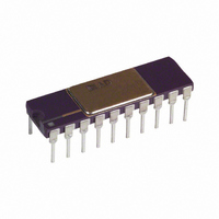
AD630AD
Description
MODULATOR / DEMODULATOR IC
Manufacturer
Analog Devices Inc
Datasheet
1.AD630JNZ.pdf
(12 pages)
Specifications of AD630AD
Rf Type
Balanced
Supply Voltage Range
± 5V To �� 16.5V
Rf Ic Case Style
DIP
No. Of Pins
20
Operating Temperature Range
-25°C To +85°C
Peak Reflow Compatible (260 C)
No
Leaded Process Compatible
No
Rohs Status
RoHS non-compliant
Function
Modulator/Demodulator
Frequency
2MHz
Package / Case
20-CDIP (0.300", 7.62mm)
Mounting Type
Through Hole
Rohs Compliant
No
Lead Free Status / RoHS Status
Contains lead / RoHS non-compliant
Available stocks
Company
Part Number
Manufacturer
Quantity
Price

Part Number:
AD630AD
Manufacturer:
ADI/亚德诺
Quantity:
20 000


BALANCED DEMODULATOR
The balanced modulator topology described above will also act as
a balanced demodulator if a double sideband suppressed carrier
waveform is applied to the signal input and the carrier signal is
applied to the reference input. The output under these circumstances
will be the baseband modulation signal. Higher order carrier
components that can be removed with a low-pass filter will
also be present. Other names for this function are synchro-
nous demodulation and phase-sensitive detection.
PRECISION PHASE COMPARATOR
The balanced modulator topologies of Figures 9a and 9b can
also be used as precision phase comparators. In this case, an ac
waveform of a particular frequency is applied to the signal input
and a waveform of the same frequency is applied to the refer-
ence input. The dc level of the output (obtained by low-pass
filtering) will be proportional to the signal amplitude and phase
difference between the input signals. If the signal amplitude is
held constant, the output can be used as a direct indication of
the phase. When these input signals are 90° out of phase, they
are said to be in quadrature and the AD630 dc output will be zero.
PRECISION RECTIFIER ABSOLUTE VALUE
If the input signal is used as its own reference in the balanced
modulator topologies, the AD630 will act as a precision recti-
fier. The high frequency performance will be superior to that
which can be achieved with diode feedback and op amps. There
are no diode drops that the op amp must “leap over” with the
commutating amplifier.
LVDT SIGNAL CONDITIONER
Many transducers function by modulating an ac carrier. A linear
variable differential transformer (LVDT) is a transducer of
this type. The amplitude of the output signal corresponds to
core displacement. Figure 11 shows an accurate synchronous
demodulation system which can be used to produce a dc voltage
that corresponds to the LVDT core position. The inherent
precision and temperature stability of the AD630 reduce
demodulator drift to a second-order effect.
REV. E
400Hz
1V
350
350
350
350
49.9
+IN
–IN
Figure 12. AC Bridge System
AD8221
REF
A
–9–
AC BRIDGE
Bridge circuits that use dc excitation are often plagued by
errors caused by thermocouple effects, 1/f noise, dc drifts in the
electronics, and line noise pick-up. One way to get around these
problems is to excite the bridge with an ac waveform, amplify the
bridge output with an ac amplifier, and synchronously demodulate
the resulting signal. The ac phase and amplitude information
from the bridge is recovered as a dc signal at the output of the
synchronous demodulator. The low frequency system noise,
dc drifts, and demodulator noise all get mixed to the carrier
frequency and can be removed by means of a low-pass filter.
Dynamic response of the bridge must be traded off against the
amount of attenuation required to adequately suppress these
residual carrier components in the selection of the filter.
Figure 12 is an example of an ac bridge system with the AD630
used as a synchronous demodulator. The bridge is excited by a
1 V 400 Hz excitation. Trace A in Figure 13 is the amplified
bridge signal. Trace B is the output of the synchronous demodu-
lator and Trace C is the filtered dc system output.
SINUSOIDAL
EXCITATION
16
17
19
20
15
2.5kH
R
R
CH B–
CH A–
R
2V p-p
A
IN
F
SEL B
B
R
IN
1
Z
9
A
AD630AR
SEL A
10
A
SCHAEVITZ
Figure 11. LVDT Signal Conditioner
+15V
+V
E1000
11
–15V
LVDT
SHIFTER
–V
PHASE
S
COMP
8
V
S
OUT
R
14
B
13
12
FOLLOWER
B
AD544
4.99k
2 F
16
14
17
10
9
1
B
2.5k
2.5k
10k
5k
4.99k
2 F
15
20
19
2 DEMODULATOR
4.99k
A
AD630
B
2 F
10k
C
12
AD630
C
13
100k
1 F
D
Related parts for AD630AD
Image
Part Number
Description
Manufacturer
Datasheet
Request
R

Part Number:
Description:
±1.7g Dual-Axis IMEMS Accelerometer Evaluation Board
Manufacturer:
Analog Devices Inc
Datasheet:

Part Number:
Description:
Inertial Sensor Evaluation System
Manufacturer:
Analog Devices Inc
Datasheet:
Part Number:
Description:
Manufacturer:
Analog Devices Inc
Datasheet:
Part Number:
Description:
Manufacturer:
Analog Devices Inc
Datasheet:
Part Number:
Description:
Manufacturer:
Analog Devices Inc
Datasheet:
Part Number:
Description:
Manufacturer:
Analog Devices Inc
Datasheet:
Part Number:
Description:
Manufacturer:
Analog Devices Inc
Datasheet:
Part Number:
Description:
Manufacturer:
Analog Devices Inc
Datasheet:
Part Number:
Description:
Manufacturer:
Analog Devices Inc
Datasheet:
Part Number:
Description:
Manufacturer:
Analog Devices Inc
Datasheet:
Part Number:
Description:
Manufacturer:
Analog Devices Inc
Datasheet:
Part Number:
Description:
Manufacturer:
Analog Devices Inc
Datasheet:
Part Number:
Description:
Manufacturer:
Analog Devices Inc
Datasheet: