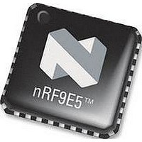
NRF9E5 NORDIC SEMICONDUCTOR, NRF9E5 Datasheet - Page 53

NRF9E5
Manufacturer Part Number
NRF9E5
Description
TRX, 430-928MHZ, MCU/ADC/PWM, SMD
Manufacturer
NORDIC SEMICONDUCTOR
Datasheet
1.NRF9E5.pdf
(108 pages)
Specifications of NRF9E5
Receiving Current
12.5mA
Transmitting Current
30mA
Data Rate
50Kbps
Frequency Range
430MHz To 928MHz
Modulation Type
GFSK
Rf Ic Case Style
QFN
No. Of Pins
32
Supply Voltage Range
1.9V To
Lead Free Status / RoHS Status
Lead free / RoHS Compliant
Available stocks
Company
Part Number
Manufacturer
Quantity
Price
Company:
Part Number:
NRF9E5C
Manufacturer:
NORDIC
Quantity:
5 000
Part Number:
NRF9E5C
Manufacturer:
NORDIC
Quantity:
20 000
PRODUCT SPECIFICATION
nRF9E5 Single Chip Transceiver with Embedded Microcontroller and ADC
16 LF CLOCK WAKEUP FUNCTIONS AND WATCHDOG
16.1 The LF Clock
The nRF9E5 contains has an internal low frequency clock CKLF that is always active.
When the crystal oscillator clocks the circuit, the CKLF is a 4kHz clock derived from
the crystal oscillator (provided the CKLFCON register is set according to crystal
frequency and prescaler. XOF and UP_CLK_FREQ respectively, see Table 22). When
no crystal oscillator clock is available, the CKLF is a low power RC oscillator
(LP_OSC) that cannot be disabled, so it will run continuously as long as VDD ≥ 1.8V.
The microprocessor can determine the phase of the CKLF clock by reading CK_CTRL
SFR 0xB6, see Table 50.
16.2 Tick Calibration
The “TICK” is an interval (in CKLF periods) that determines the resolution of the
watchdog and the RTC wakeup timer. The tick is nominally 1ms (4 CKLF cycles).
When the CPU is active and in power down modes where the chip still has crystal clock,
the “TICK” will be as accurate as the crystal oscillator. When the CKLF switches to the
RC oscillator (LP_OSC) in deep power down modes, the tick will no longer be accurate.
The LP_OSC clock source is very inaccurate, and the nominal TICK may vary from
0.7ms to 4ms depending production lot, temperature and supply voltage. That means
that Watchdog and RTC wakeup may not be used for any accurate timing functions if
these power down modes are used.
The accuracy can be improved by calibrating the TICK value at regular intervals. The
register TICK_DV controls how many CKLF periods elapse between each TICK. The
frequency of the LP_OSC (between 1 kHz and 5 kHz) can be measured by timer2 in
capture mode with t2ex enabled (EXEN2=1). The signal connected to t2ex has exactly
half the frequency of LP_OSC. The 16-bit difference between two consecutive captures
in SFR-registers{RCAP2H,RCAP2L} is proportional to the LP_OSC period. For details
about timer2 see ch. 18.8.3 and Figure 21 Timer 2 – Timer/Counter with Capture
TICK is controlled by SFRs 0xB5 and 0xBF
Main office: Nordic Semiconductor ASA - Vestre Rosten 81, N-7075 Tiller, Norway -Phone +4772898900 - Fax +4772898989
Revision: 1.3
Addr
SFR
BF
B5
R/W
R/W
R/W
#bit
8
6
Table 43 TICK control register - SFR 0xB5.
Init
Hex
03
27
Name
TICK_DV
CKLFCON
Page 53 of 108
Function
Divider that’s used in generating TICK from CKLF
frequency.
T
The default value gives a TICK of 1ms nominal as
default (with CKLF derived from crystal oscillator).
Configure CKLF generation with crystal frequency
and prescaler value. Note this register only controls the
generation of CKLF, not the actual prescaler values.
5-3: Should be set equal to XOF, Table 22
2: Should be set equal to XO_DIRECT, Table 22
1-0: Should be set equal to UP_CLK_FREQ, Table 22
TICK
= (1 + TICK_DV) / f
CKLF
June 2006


