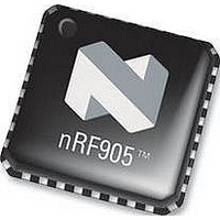
NRF905 NORDIC SEMICONDUCTOR, NRF905 Datasheet - Page 24

NRF905
Manufacturer Part Number
NRF905
Description
IC, TRANSCEIVER, 430 928MHZ, SMD
Manufacturer
NORDIC SEMICONDUCTOR
Datasheet
1.NRF905.pdf
(42 pages)
Specifications of NRF905
Transmitting Current
9mA
Data Rate
50Kbps
Frequency Range
430MHz To 928MHz
Modulation Type
GFSK
Sensitivity Dbm
-100dBm
Rf Ic Case Style
QFN
No. Of Pins
32
Supply Voltage Range
1.9V To 3.6V
Output Power
10dBm
Rohs Compliant
Yes
Lead Free Status / RoHS Status
Lead free / RoHS Compliant
Available stocks
Company
Part Number
Manufacturer
Quantity
Price
Part Number:
NRF905
Manufacturer:
NORDIC
Quantity:
20 000
Company:
Part Number:
NRF905-REEL
Manufacturer:
NORDIC
Quantity:
20 000
Part Number:
NRF905-REEL
Manufacturer:
NORDIC
Quantity:
20 000
Company:
Part Number:
NRF905C
Manufacturer:
NORDIC
Quantity:
10 615
PRODUCT SPECIFICATION
nRF905 Single Chip 433/868/915 MHz Radio Transceiver
8 PERIPHERAL RF INFORMATION
8.1
Tolerance includes initially accuracy and tolerance over temperature and aging.
To achieve a crystal oscillator solution with low power consumption and fast start-up
time, it is recommended to specify the crystal with a low value of crystal load
capacitance. Specifying a lower value of crystal parallel equivalent capacitance,
Co=1.5pF is also good, but this can increase the price of the crystal itself. Typically
Co=1.5pF at a crystal specified for Co_max=7.0pF.
The crystal load capacitance, C
C
C
into the XC1 and XC2 pin respectively; the value is typical 1pF.
8.2
An external reference clock, such as a MCU clock, may be used instead of a crystal.
The clock signal should be applied directly to the XC1 pin, the XC2 pin can be left
high impedance. When operating with an external clock instead of a crystal the clock
must be applied in standby mode to achieve low current consumption. If the device is
set into standby mode with no external clock or crystal then the current consumption
will increase up to a maximum of 1mA.
8.3
By default a microprocessor clock output is provided. Providing an output clock will
increase the current consumption in standby mode. The current consumption in
standby will depend on frequency and load of external crystal, frequency of output
clock and capacitive load of the provided output clock. Typical current consumption
values are found in Table 5
Main office: Nordic Semiconductor ASA
Revision: 1.4
1
PCB2
and C
Frequency
12MHz
16MHz
20MHz
Crystal Specification
External Clock Reference
Microprocessor Output Clock
4MHz
8MHz
are the layout parasitic on the circuit board. C
2
are 0603 SMD capacitors as shown in the application schematics. C
C
L
C
C
1
1
'
'
8pF – 16pF
8pF – 16pF
8pF – 16pF
8pF – 16pF
8pF – 16pF
C
C
2
2
Table 12 Crystal specification of nRF905.
'
'
C
,
L
where
.
- Vestre Rosten 81, N-7075 Tiller, Norway
L
, is given by:
C
1
150
100
100
100
100
'
ESR
C
1
Page 24 of 42
C
PCB
1
7.0pF
7.0pF
7.0pF
7.0pF
7.0pF
C
C
0max
I
1
and
I1
and C
C
2
'
868/915 MHz
Tolerance @
I2
C
- Phone +4772898900 -Fax +4772898989
2
are the capacitance seen
30ppm
30ppm
30ppm
30ppm
30ppm
C
PCB
2
C
I
Tolerance @
2
433 MHz
60ppm
60ppm
60ppm
60ppm
60ppm
PCB1
June 2006
and


