AD532SD Analog Devices Inc, AD532SD Datasheet - Page 5
AD532SD
Manufacturer Part Number
AD532SD
Description
Multiplexer IC
Manufacturer
Analog Devices Inc
Specifications of AD532SD
Ic Function
Analog Multiplier/Divider IC
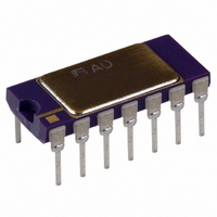
Package/case
14-CDIP
Accuracy
1 %
Leaded Process Compatible
No
Number Of Channels
4
Output Voltage
13V
Peak Reflow Compatible (260 C)
No
Supply Voltage Max
18V
Rohs Status
RoHS non-compliant
Function
Analog Multiplier/Divider
Number Of Bits/stages
4-Quadrant
Package / Case
14-CDIP (0.300", 7.62mm)
Lead Free Status / RoHS Status
Contains lead / RoHS non-compliant
Available stocks
Company
Part Number
Manufacturer
Quantity
Price

Company:
Part Number:
AD532SD/883B
Manufacturer:
ADI
Quantity:
676


DYNAMIC CHARACTERISTICS
The closed loop frequency response of the AD532 in the multi-
plier mode typically exhibits a 3 dB bandwidth of 1 MHz and
rolls off at 6 dB/octave thereafter. Response through all inputs is
essentially the same as shown in Figure 7. In the divide mode,
the closed loop frequency response is a function of the absolute
value of the denominator voltage as shown in Figure 8.
Stable operation is maintained with capacitive loads to 1000 pF
in all modes, except the square root for which 50 pF is a safe
upper limit. Higher capacitive loads can be driven if a 100 Ω
resistor is connected in series with the output for isolation.
0.01
0.1
1.0
1.0
0.1
10
10k
10k
100k
100k
R
FREQUENCY
FREQUENCY
V
L
X
2k
1V
C
L
0pF
R
V
Hz
Hz
Z
L
1M
1M
2k
0.1
V
V
C
X
V
X
L
X
10V
SIN T
5V
1000pF
10M
10M
POWER SUPPLY CONSIDERATIONS
Although the AD532 is tested and specified with ± 15 V dc
supplies, it may be operated at any supply voltage from ± 10 V
to ± 18 V for the J and K versions, and ± 10 V to ± 22 V for the
S version. The input and output signals must be reduced pro-
portionately to prevent saturation; however, with supply voltages
below ± 15 V, as shown in Figure 9. Since power supply sensitiv-
ity is not dependent on external null networks as in other
conventionally nulled multipliers, the power supply rejection
ratios are improved from 3 to 40 times in the AD532.
NOISE CHARACTERISTICS
All AD532s are screened on a sampling basis to assure that
output noise will have no appreciable effect on accuracy. Typi-
cal spot noise vs. frequency is shown in Figure 10.
12
10
5
4
3
2
1
0
8
4
6
10
10
SATURATED OUTPUT
SWING
12
POWER SUPPLY VOLTAGE
100
FOR 1% LINEARITY
MAX X OR Y INPUT
14
FREQUENCY
1k
16
Hz
18
Volts
10k
20
AD532
100k
22
Related parts for AD532SD
Image
Part Number
Description
Manufacturer
Datasheet
Request
R

Part Number:
Description:
±1.7g Dual-Axis IMEMS Accelerometer Evaluation Board
Manufacturer:
Analog Devices Inc
Datasheet:

Part Number:
Description:
Inertial Sensor Evaluation System
Manufacturer:
Analog Devices Inc
Datasheet:
Part Number:
Description:
Manufacturer:
Analog Devices Inc
Datasheet:
Part Number:
Description:
Manufacturer:
Analog Devices Inc
Datasheet:
Part Number:
Description:
Manufacturer:
Analog Devices Inc
Datasheet:
Part Number:
Description:
Manufacturer:
Analog Devices Inc
Datasheet:
Part Number:
Description:
Manufacturer:
Analog Devices Inc
Datasheet:
Part Number:
Description:
Manufacturer:
Analog Devices Inc
Datasheet:
Part Number:
Description:
Manufacturer:
Analog Devices Inc
Datasheet:
Part Number:
Description:
Manufacturer:
Analog Devices Inc
Datasheet:
Part Number:
Description:
Manufacturer:
Analog Devices Inc
Datasheet:
Part Number:
Description:
Manufacturer:
Analog Devices Inc
Datasheet:
Part Number:
Description:
Manufacturer:
Analog Devices Inc
Datasheet: