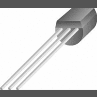
LM336BZ-5.0 National Semiconductor, LM336BZ-5.0 Datasheet - Page 5

LM336BZ-5.0
Manufacturer Part Number
LM336BZ-5.0
Description
Voltage Reference
Manufacturer
National Semiconductor
Specifications of LM336BZ-5.0
Peak Reflow Compatible (260 C)
No
Current Rating
10A
Leaded Process Compatible
No
Mounting Type
Through Hole
Supply Current
600mA
Package / Case
3-TO-92
Lead Free Status / RoHS Status
Contains lead / RoHS non-compliant
Available stocks
Company
Part Number
Manufacturer
Quantity
Price
Company:
Part Number:
LM336BZ-5.0
Manufacturer:
FAIRCHILD
Quantity:
59 000
Typical Performance Characteristics
(Continued)
Forward Characteristics
00571623
Application Hints
The LM136-5.0 series voltage references are much easier to
use than ordinary zener diodes. Their low impedance and
wide operating current range simplify biasing in almost any
circuit. Further, either the breakdown voltage or the tempera-
ture coefficient can be adjusted to optimize circuit perfor-
mance.
Figure 1 shows an LM136-5.0 with a 10k potentiometer for
adjusting the reverse breakdown voltage. With the addition
of R1 the breakdown voltage can be adjusted without affect-
ing the temperature coefficient of the device. The adjustment
range is usually sufficient to adjust for both the initial device
tolerance and inaccuracies in buffer circuitry.
If minimum temperature coefficient is desired, four diodes
can be added in series with the adjustment potentiometer as
shown in Figure 2. When the device is adjusted to 5.00V the
temperature coefficient is minimized. Almost any silicon sig-
nal diode can be used for this purpose such as a 1N914,
1N4148 or a 1N457. For proper temperature compensation
the diodes should be in the same thermal environment as
the LM136-5.0. It is usually sufficient to mount the diodes
00571610
near the LM136-5.0 on the printed circuit board. The abso-
lute resistance of the network is not critical and any value
FIGURE 2. Temperature Coefficient Adjustment
from 2k to 20k will work. Because of the wide adjustment
±
(Trim Range =
0.5V Typical)
range, fixed resistors should be connected in series with the
pot to make pot setting less critical.
00571609
FIGURE 1. LM136-5.0 with Pot for Adjustment of
±
Breakdown Voltage (Trim Range =
1.0V Typical)
5
www.national.com


