20.23.9.024.0000 FINDER, 20.23.9.024.0000 Datasheet
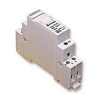
POWER RELAY, SPST, 24VDC, 16A, DIN RAIL

20.23.9.024.0000

Manufacturer Part Number
20.23.9.024.0000
Description
POWER RELAY, SPST, 24VDC, 16A, DIN RAIL
Manufacturer
FINDER
Datasheet

Specifications of 20.23.9.024.0000

Coil Voltage Vdc Nom
24V
Contact Current Max
30A
Contact Voltage Ac Nom
250V
Coil Resistance
105ohm
Contact Configuration
DPCO
Coil Type
DC
Coil Current
230mA
Nom Operating Power
5W
Lead Free Status / RoHS Status
Lead free / RoHS Compliant
Features
1 or 2 Pole 16 A Step relays for direct 35 mm
rail (EN 50022) mounting
F
S
Contact specification
Contact configuration
Rated current/Maximum peak current
Rated voltage/Maximum switching voltage V AC
Rated load AC1
Rated load AC15 (230 V AC)
Nominal lamp rating:incandescent (230 V) W
Minimum switching load
Standard contact material
Coil specification
Nominal voltage (U
Rated power AC/DC
Operating range
Technical data
Mechanical life
Electrical life at rated load in AC1
Minimum/Maximum impulse duration
Insulation between coil and contacts (1.2/50 µs) kV
Ambient temperature range
Protection category
Approvals (according to type)
17.4 mm wide
Test button with mechanical indicators
Choice of 6 switching sequences
AC coils and DC coils
Identification label
Possible to connect illuminated push
buttons with the additional part 026.00
35 mm rail (EN 50022) mount
Cadmium free contact material
OR
EE
“General technical information” page V
UL H
uncompensated fluorescent (230 V) W
ORSEPOWER AND
compensated fluorescent (230 V) W
N
)
P
ILOT
halogen (230 V) W
D
V AC (50/60 Hz)
UTY RATINGS
VA (50 Hz)/W
mW (V/mA)
cycles
cycles
V DC
AC
DC
VA
VA
°C
A
0.1s/1h (according to EN60669) 0.1s/1h (according to EN60669) 0.1s/1h (according to EN60669)
Single phase switch 1 NO
35 mm rail (EN 50022) mount
(SPST-NO)
17.4
12 - 24 - 48 - 110
1 NO (SPST-NO)
1,000 (10/10)
(0.9…1.1)U
250/400
300 · 10
100 · 10
–40…+40
A2
A1
20.21
16/30
4,000
2,000
1,000
2,000
6.5/5
AgNi
IP 20
750
750
26.5
4
2
43.5
1
58.4
3
3
N
(0.85…1.1)U
8 - 12 - 24 - 48 - 110 - 120 - 230 - 240
20 Series - Modular step relays 16 A
Double phase switch
35 mm rail (EN 50022) mount
20.22, 24, 26, 28
17.4
N
12 - 24 - 48 - 110
2 NO (DPST-NO)
1,000 (10/10)
(50 Hz)/(0.9…1.1)U
(0.9…1.1)U
–40…+40
250/400
300 · 10
100 · 10
A1
A2
16/30
4,000
2,000
1,000
2,000
6.5/5
AgNi
IP 20
750
750
26.5
4
2
1
43.5
58.4
4
3
3
3
N
N
(60 Hz)
1NO+1NC (SPST-NO+SPST-NC)
Double phase switch
35 mm rail (EN 50022) mount
1NO+1NC (SPST-NO+SPST-NC)
17.4
12 - 24 - 48 - 110
1,000 (10/10)
(0.9…1.1)U
–40…+40
A1
A2
250/400
300 · 10
100 · 10
20.23
16/30
4,000
2,000
1,000
2,000
6.5/5
AgNi
IP 20
750
750
26.5
2
4
1
43.5
3
58.4
4
3
3
N
1

Related parts for 20.23.9.024.0000

20.23.9.024.0000 Summary of contents

Page 1

... V) W halogen (230 V) W Minimum switching load mW (V/mA) Standard contact material Coil specification Nominal voltage ( (50/60 Hz Rated power AC/DC VA (50 Hz)/W Operating range AC DC Technical data Mechanical life cycles Electrical life at rated load in AC1 cycles Minimum/Maximum impulse duration Insulation between coil and contacts (1.2/50 µ ...

Page 2

... Other data Power lost to the environment with rated current and coil deenergised W 1.3 (20.21, 20.23, 20.28) Screw torque Max. wire size If the coil is operated for a prolonged period of time, adaquate ventilation of the relays must be provided - suggested gap between adjacent relays ...

Page 3

... Type 026.00 Sealed construction, 7.5 cm insulated flexible wire termination. Sheet of marker tags, plastic, 24 tags, 9x17 mm 020.24 20 Series - Modular step relays Example supply voltage. 13 Example of wiring diagram of type 026.00 This module is necessary when using between 1 and a maximum of 15 illuminated push buttons in the coil circuit (Each 1.5 mA max, 230 V AC). ...

Page 4

...

Related keywords