62.82.8.230.0000 FINDER, 62.82.8.230.0000 Datasheet

RELAY, DPCO, 230VAC

62.82.8.230.0000

Manufacturer Part Number
62.82.8.230.0000
Description
RELAY, DPCO, 230VAC
Manufacturer
FINDER
Datasheet

Specifications of 62.82.8.230.0000

Relay Type
Power
Coil Voltage Vac Nom
230V
Contact Current Max
30A
Contact Voltage Ac Nom
250V
Coil Resistance
7.25kohm
Coil Type
AC Coil
Coil Current
10.5mA
Nom Operating Power
2.2VA
Relay
RoHS Compliant
Contact Configuration
DPCO
Rohs Compliant
Yes
8
62.22
22.2
38.2
Printed circuit mount
16 A Power relay
Features
* Distance between contacts ≥ 3 mm
** With the AgSnO
Contact specification
Contact configuration
Rated current/Maximum peak current
Rated voltage/Maximum switching voltage V AC
Rated load AC1
Rated load AC15 (230 V AC)
Motor rating (230/400 V AC)
Breaking capacity DC1: 30/110/220 V
Minimum switching load
Standard contact material
Coil specification
Nominal voltage (U
Rated power AC/DC
Operating range
Holding voltage
Must drop-out voltage
Technical data
Mechanical life AC/DC
Electrical life at rated load AC1
Operate/release time
Insulation between coil and contacts (1.2/50 µs) kV
Dielectric strength between open contacts
Ambient temperature range
Environmental protection
Approvals (according to type)
2 & 3 Pole changeover contacts
or NO (
AC coils & DC coils
Reinforced insulation between coil and
contacts according to EN 60335-1,
with 6 mm clearance & 8 mm creepage
distance
SELV coil-contact separator option
Cadmium Free contact material options
8
(EN 60730-1).
peak current is 120 A - 5 ms (NO contact).
8
62.23
11.1
38.2
3 mm contact gap)
8
2
8.65 7.6 8.3
N
material the maximum
)
35.8
5.5 5.75
V AC (50/60 Hz)
VA (50 Hz)/W
62.2x-0300
8.65 7.6 8.3 11.25
mW (V/mA)
35.8
AC/DC
AC/DC
cycles
cycles
V DC
V AC
kW
AC
DC
VA
VA
ms
°C
A
A
2 & 3 pole changeover contact
PCB mount
Copper side view
A1
12 14
1
11
2 CO (DPDT)
8
12
14
11
A1
7
4
A
1
4
7
A
0.8/—
62.22
22.2
38.2
32
34
31
A2
B
10 · 10
62.22 / 62.23
32 34
3 6
3
6
9
B
0.8 U
0.2 U
1,000 (10/10)
8
31
(0.8…1.1)U
(0.8…1.1)U
9
16/0.6/0.4
A2
–40…+70
100 · 10
16/30**
250/400
2.2/1.3
AgCdO
10/10
4,000
1,500
5.6
5.8
7.6
8.8
8
750
N
N
RT I
6
/0.6 U
/0.1 U
/30 · 10
6
6 - 12 - 24 - 48 - 60 - 110 - 120 - 230 - 240 - 400
Copper side view
12 14 22 24 32 34
A1
3
1
6 - 12 - 24 - 48 - 60 - 110 - 125 - 220
3 CO (3PDT)
N
N
11
7
12
14
N
N
8
11
A1
4
0.8/1.5
1
4
7
A
6
A
11.1
62.23
2 5
22
24
21
38.2
21
8
11.1
2
5
8
32
34
31
A2
B
3 6
3
6
9
B
62 Series - Power relays 16 A
8
31
9
A2
5.6
5.8
8
7.6
8.8
2 NO (DPST-NO), ≥ 3 mm* 3 NO (3PST-NO), ≥ 3 mm*
2 & 3 pole normally open contact
(≥ 3 mm contact gap)
PCB mount
A1
Copper side view
11
62.22 - 0300
7
14
8
14
11
A1
4
62.22-0300 / 62.23-0300
4
7
A
A
0.8/—
22.2
38.2
34
31
A2
B
10 · 10
6
9
B
8
0.8 U
0.2 U
31
1,000 (10/10)
(0.85…1.1)U
(0.85…1.1)U
9
34
6
A2
16/1.1/0.7
–40…+50
250/400
100 · 10
16/30**
AgCdO
11.4
7.6
8.8
8
4,000
2,500
20/4
750
3/3
N
N
RT I
6
/0.6 U
/0.1 U
/30 · 10
6
A1
Copper side view
3
11
62.23 - 0300
7
14
8
14
11
N
N
A1
N
N
4
0.8/1.5
A
4
7
A
6
11.1
24
21
38.2
21
8
24
11.1
5
8
5
34
31
A2
B
B
6
9
8
31
9
34
6
A2
11.4
7.6
8.8
8
95
62

Related parts for 62.82.8.230.0000

62.82.8.230.0000 Summary of contents

Page 1

... AC (0.8…1.1 (0.8…1.1)U N 0 0 cycles 10 · /30 · cycles 100 · 10/ 1,500 °C –40…+ Series - Power relays 16 A 62.22-0300 / 62.23-0300 2 & 3 pole normally open contact • (≥ contact gap) PCB mount • 38 ...

Page 2

... N DC (0.8…1.1)U N AC/DC 0 AC/DC 0 cycles 10 · /30 · cycles 100 · 10/ 1,500 °C –40…+ Series - Power relays 16 A 62.32-0300 / 62.33-0300 2 & 3 pole normally open contact • (≥ contact gap) Plug-in / Faston 187 • 62.32-0300 62.33-0300 35 ...

Page 3

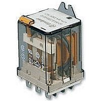
... AC (0.8…1.1 (0.8…1.1)U N 0 0 · /30 · 100 · 10/10 6 1,500 °C –40…+ Series - Power relays 16 A 62.82-0300 / 62.83-0300 2 & 3 pole normally open contact • (≥ contact gap) Flange mount / Faston 250 • ...

Page 4

... Top 35 mm rail mount Lockable test button and mechanical flag indicator (0040) The dual-purpose Finder test button can be used in two ways: Case 1) The plastic pip (located directly above the test button) remains intact. In this case, when the test button is pushed, the contacts operate. When the test button is released the contacts return to their former state ...

Page 5

... When switching a resistive load (DC1) having voltage and current values under the curve, an electrical life of ≥ 100·10 • In the case of DC13 loads, the connection of a diode in parallel with the load will permit a similar electrical life as for a DC1 load. Note: the release time of the load will be increased. 62 Series - Power relays 16 A insulation rated voltage V 400 ...

Page 6

... coil operating range v ambient temperature Normally open contacts U 2 1.5 1 1 -20 (° Max. permitted coil voltage Min. pick-up voltage with coil at ambient temperature. 62 Series - Power relays 16 A Coil Operating range Resistance Rated coil code min max V V Ω 8.006 4.8 6.6 4.6 8.012 9.6 13 ...

Page 7

... Accessories Mounting adaptor for types 62.3x and 62.8x.xxxx.xxx9 (M4) 47,2 062.10 47,2 M4 062.10 Flange mounting adaptor for types 62.3x and 62.8x.xxxx.xxx9 41 062.60 52.3 062.60 Sheet of marker tags for 62 series relays, plastic, 72 tags, 6x12 mm 060.72 62 Series - Power relays 16 A 062.10 062.60 060.72 62 101 ...

Page 8

... LED + Diode (+A2, non standard polarity) * Modules in Black LED + Diode (+A2, non standard polarity) housing are LED + Varistor available on request. LED + Varistor LED + Varistor RC circuit RC circuit RC circuit Residual current by-pass (62 kΩ/1W) 102 92 Series - Sockets and accessories for 62 series relays ° AWG 60.9 40 35.5 30.25 27 COM ...

Page 9

... How to code and identify retaining clip and packaging options for sockets. Code options according to the last three letters Series - Sockets and accessories for 62 series relays 92.13 (blue) 62.32, 62. 250 V (10 A max for each contact circuit) ≥ 2 °C –40…+ 11.1 11 ...

Page 10

...

Related keywords