240D25 OPTO 22, 240D25 Datasheet - Page 19
240D25
Manufacturer Part Number
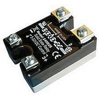
240D25
Description
SSR, PANEL MOUNT, 280VAC, 32VDC, 25A
Manufacturer
OPTO 22
Specifications of 240D25
Control Voltage Range
3VDC To 32VDC
Operating Voltage Range
24VAC To 280VAC
Load Current
25A
Isolation Voltage
4000Vrms
Control Voltage Type
DC
Relay Terminals
Screw
Peak Surge Current
250A
Brand/series
DC Series
Current, Rating
25 A
Current, Surge
250 A (Max.)
Dimensions
1.75 in. W x 2.25 in. H x 0.77 in. T
Function
Power
Mounting Type
PCB
Relay Type
Solid State
Standards
UL, CSA, CE
Termination
Quick Connect
Voltage, Control
240 VAC
Voltage, Drop, On-state
1 VAC
Control Voltage Max
32V
Rohs Compliant
Yes
Lead Free Status / RoHS Status
Lead free / RoHS Compliant
Available stocks
Company
Part Number
Manufacturer
Quantity
Price


Heater Loads
Care should be taken in selecting a SSR for driving a heater
load if the load is cycled on and off in a continuous manner as
might occur in a temperature control application. Constant
cycling can cause thermal fatigue in the thyristor chip at the
point where the chip bonds to the lead frame. Opto 22
employs a thick copper lead frame for mounting the SCR chips
in the power series SSRs to eliminate thermal fatigue failures.
In addition, Opto 22 recommends operating any SSR at 75%
rated current for cycling heater loads to ensure complete
reliability.
The following table is a guide to selecting the proper SSR for a
given heater load.
Single-Phase Reversing Motor Control
The circuit diagram below illustrates a typical 1 Ø motor
winding inductance and the phase shift capacitor can cause
twice-line voltage to appear across the open SSR. A 240-volt
SSR should be used for a 120-volt line. During the transition
period when one SSR is turned on and the other SSR is going
off, both SSRs may be on. In this case, the capacitor may
discharge through the two SSRs, causing large currents to
flow, which may destroy the SSRs. The addition of RL as shown
will protect the SSRs from the short circuit capacitor discharge
current.
© 2006–2011 Opto 22. All rights reserved. Dimensions and specifications are subject to change. Brand or product names used herein are trademarks or registered trademarks of their respective companies or organizations.
Solid-State Relays
Current Rating
Nominal SSR
10 480V
10 480V
10-Amp
25-Amp
45-Amp
2-Amp
4-Amp
800-321-6786 • 951-695-3000 • FAX 951-695-3095 • sales@opto22.com •
Recommended
Heater Current
Maximum
2½-Amp
7½-Amp
1½-Amp
18-Amp
35-Amp
8-Amp
8-Amp
Single-Phase Reversing Motor Control (cont.)
The resistors are unnecessary if the control circuit is designed
to ensure that one SSR is off before the other SSR is on.
Three-Phase Motor Control
Three-phase motors may be controlled by solid-state relays as
shown. A third SSR as shown is optional, but not necessary.
The control windings may be connected in series or parallel.
Care should be taken to ensure that the surge current drawn
by the motor does not exceed the surge current rating of the
SSR.
Opto 22 • 43044 Business Park Drive • Temecula, CA 92590-3614 • www.opto22.com
800-835-6786 • 951-695-3080 • FAX 951-695-3017 • support@opto22.com
240 Volt Three-Phase Motor
SSR MODEL
Z240D10
240D10
240A10
240D25
240A25
240D45
MOTOR
3/4 HP
3/4 HP
3/4 HP
2 HP
2 HP
3 HP
PAGE
19
Related parts for 240D25
Image
Part Number
Description
Manufacturer
Datasheet
Request
R

Part Number:
Description:
SSR, PANEL MOUNT, 280VAC, 32VDC, 10A
Manufacturer:
OPTO 22
Datasheet:
Part Number:
Description:
SSR, PANEL MOUNT, 280VAC, 32VDC, 25A
Manufacturer:
OPTO 22
Datasheet:
Part Number:
Description:
SSR, PANEL MOUNT, 280VAC, 32VDC, 45A
Manufacturer:
OPTO 22
Datasheet:
Part Number:
Description:
SSR, PANEL MOUNT, 280VAC, 32VDC, 45A
Manufacturer:
OPTO 22
Datasheet:

Part Number:
Description:
SSR, 10A, 240VAC
Manufacturer:
OPTO 22
Datasheet:

Part Number:
Description:
Programmable Logic Controller
Manufacturer:
OPTO 22
Datasheet:

Part Number:
Description:
Programmable Logic Controller
Manufacturer:
OPTO 22
Datasheet:

Part Number:
Description:
Solid State Relays, Accessories
Manufacturer:
OPTO 22
Datasheet:
Part Number:
Description:
Solid State Relays, Accessories
Manufacturer:
OPTO 22
Datasheet:
