240D25 OPTO 22, 240D25 Datasheet - Page 22
240D25
Manufacturer Part Number
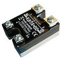
240D25
Description
SSR, PANEL MOUNT, 280VAC, 32VDC, 25A
Manufacturer
OPTO 22
Specifications of 240D25
Control Voltage Range
3VDC To 32VDC
Operating Voltage Range
24VAC To 280VAC
Load Current
25A
Isolation Voltage
4000Vrms
Control Voltage Type
DC
Relay Terminals
Screw
Peak Surge Current
250A
Brand/series
DC Series
Current, Rating
25 A
Current, Surge
250 A (Max.)
Dimensions
1.75 in. W x 2.25 in. H x 0.77 in. T
Function
Power
Mounting Type
PCB
Relay Type
Solid State
Standards
UL, CSA, CE
Termination
Quick Connect
Voltage, Control
240 VAC
Voltage, Drop, On-state
1 VAC
Control Voltage Max
32V
Rohs Compliant
Yes
Lead Free Status / RoHS Status
Lead free / RoHS Compliant
Available stocks
Company
Part Number
Manufacturer
Quantity
Price


PAGE
22
Q : What agency approvals do your SSRs carry?
A: In general, Opto 22 relays carry UL, CSA, and CE approval.
See http://support.opto22.com. Additionally, some SSRs
contain VDE-approved optocouplers; contact Opto 22 for
more information.
FAQ: SSR Troubleshooting
Q : My SSR does not function anymore. What may
have happened?
A: There is no “normal” mode of failure for SSRs. They just stop
working, by refusing to turn on or off. An improper installation
is often to blame for an SSR failure, as these are very simple,
reliable devices. If you have a failed SSR, it is important to look
at the normal operating parameters of that relay within the
larger system to make sure that the relay being used is
appropriate to the application, and that the relay is being
properly installed in the system. The three most common
causes of SSR failure are as follows:
•
•
•
Q : How can I test my SSR?
A: It is not possible to test an SSR by the same methods used
to test mechanical relays; a typical SSR will always show an
infinite impedance to a resistance meter placed across the
output terminals. There are a few reasons for this. First, the SSR
requires a small amount of power to operate, derived from
whatever voltage source is placed on the load terminals. A
Opto 22 • 43044 Business Park Drive • Temecula, CA 92590-3614 • www.opto22.com
© 2006–2011 Opto 22. All rights reserved. Dimensions and specifications are subject to change. Brand or product names used herein are trademarks or registered trademarks of their respective companies or organizations.
800-321-6786 • 951-695-3000 • FAX 951-695-3095 • sales@opto22.com •
SSR improperly matched to load. The relay was
destroyed by overheating from carrying too much
current too long.
SSR insufficiently protected. Remember, a
semiconductor is less tough than a simple metal contact.
Reverse voltages exceeding the PRV rating of the relay
will cause damage. Voltage spikes on the switched line,
perhaps from inductive kickback, may have destroyed
one or more of the internal switching devices.
Remember to use snubbers, transorbs, MOVs, and/or
commutating diodes on highly inductive loads.
SSR improperly installed. The SSR was not mounted to
a large enough heat sink, or no thermal compound was
used, causing the relay to overheat. Also, insufficient
tightening of the load terminals can cause arcing and
ohmic heating of the relay. Opto 22 recommends 18
inch-pounds of torque on the load screw terminals.
Similar failures have also been attributed to the use of
crimp-on terminal lugs or spades; make sure such
terminals are tightly crimped, and even drip some solder
into the joint to ensure good electrical contact and
protection from corrosion.
800-835-6786 • 951-695-3080 • FAX 951-695-3017 • support@opto22.com
typical multimeter will not supply sufficient voltage to cause
the relay to change state. Second, AC SSRs contain a zero-
crossing circuit, which will not allow them to change state
unless zero voltage is applied. Most test equipment will supply
a DC voltage to the relay, and the relay will thus never see the
zero it requires to change state. To test an SSR, it is best to
operate it at the actual line voltage it will be used at, driving a
load such as a large light bulb.
Q : I have an SSR driving a load. The load turns on
okay, but never seems to turn off, unless I remove
power from the relay entirely. What might be hap-
pening?
A: This is normally a problem when using an SSR with a high-
impedance load, such as a neon lamp or a small solenoid.
Loads like these often have relatively large initial currents, but
relatively small “hold in” currents. The result is that the off-state
leakage current through the relay (see previous section) is
insufficient to cause the load to turn on to start with, but
sufficient to keep it on, once started. The solution is to place a
power resistor, sized for 8–10 times the rated maximum
leakage current for the SSR in parallel with the load. Make sure
that this resistor has a high enough power rating for the
application. For example, for a 5 mA leakage current at 120
VAC, a resistor drawing 50 mA would be desirable. Using
Ohm’s Law, the resistor value becomes 2,400 ohms. This
resistor will dissipate 6 watts, so a 7.5 or 10-watt size power
resistor should be used.
Q : I have a new AC SSR driving a solenoid. It turns on
okay once, but will not turn on again. What is going
on?
A: Some solenoids, some types of halogen lights, and some
types of strobe lights incorporate a diode in series with the coil
or filament. This causes the light to behave as a half-wave
rectifier. Opto 22 SSRs have a built-in R-C snubber circuit in
parallel with the output. The capacitor in this circuit charges
up but cannot discharge through the series diode, causing a
voltage to appear across the SSR terminals. Because the SSR
must see a zero voltage across the terminals to come on, it
can’t turn on again in this situation. The solution here would
be to put a high-value resistor (several tens of Kohms) across
the terminals of the relay, to allow the capacitor to drain its
charge.
Solid-State Relays
Related parts for 240D25
Image
Part Number
Description
Manufacturer
Datasheet
Request
R

Part Number:
Description:
SSR, PANEL MOUNT, 280VAC, 32VDC, 10A
Manufacturer:
OPTO 22
Datasheet:
Part Number:
Description:
SSR, PANEL MOUNT, 280VAC, 32VDC, 25A
Manufacturer:
OPTO 22
Datasheet:
Part Number:
Description:
SSR, PANEL MOUNT, 280VAC, 32VDC, 45A
Manufacturer:
OPTO 22
Datasheet:
Part Number:
Description:
SSR, PANEL MOUNT, 280VAC, 32VDC, 45A
Manufacturer:
OPTO 22
Datasheet:

Part Number:
Description:
SSR, 10A, 240VAC
Manufacturer:
OPTO 22
Datasheet:

Part Number:
Description:
Programmable Logic Controller
Manufacturer:
OPTO 22
Datasheet:

Part Number:
Description:
Programmable Logic Controller
Manufacturer:
OPTO 22
Datasheet:

Part Number:
Description:
Solid State Relays, Accessories
Manufacturer:
OPTO 22
Datasheet:
Part Number:
Description:
Solid State Relays, Accessories
Manufacturer:
OPTO 22
Datasheet:
