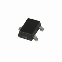
A1384LLHLT-T Allegro Microsystems Inc, A1384LLHLT-T Datasheet - Page 5

A1384LLHLT-T
Manufacturer Part Number
A1384LLHLT-T
Description
IC SENSOR HALL EFFECT SOT23-W
Manufacturer
Allegro Microsystems Inc
Series
A138xr
Type
Linear - Programmabler
Datasheet
1.A1381ELHLT-T.pdf
(19 pages)
Specifications of A1384LLHLT-T
Sensing Range
2mV/G ~ 3mV/G
Voltage - Supply
4.5 V ~ 5.5 V
Current - Supply
8mA
Current - Output (max)
10mA
Output Type
Analog, Ratiometric
Operating Temperature
-40°C ~ 150°C
Package / Case
SOT-23W
Peak Reflow Compatible (260 C)
Yes
Accuracy %
1.5%
Supply Voltage
5V
Output Current
2mA
Termination Type
SMD
Bandwidth
27kHz
Supply Voltage Max
5.5V
Sensitivity
2 To 3 MV/G
Leaded Process Compatible
Yes
No. Of Pins
3
Hall Effect Type
Linear
Supply Voltage Min
4.5V
Operating Temperature Max
150°C
Rohs Compliant
Yes
Filter Terminals
SMD
Operating Temperature Min
-40°C
Lead Free Status / RoHS Status
Lead free / RoHS Compliant
Features
-
Lead Free Status / RoHS Status
Lead free / RoHS Compliant, Lead free / RoHS Compliant
Other names
620-1199-2
A1381, A1382,
A1383, and A1384
1
2
3
4
5
6
7
V
8
9
specified value of Step
10
11
to and including Sens(max). See Characteristic Definitions section.
12
13
14
15
See Characteristic Definitions section.
f
Unit of measure (phase degrees) in reference to the magnetic input signal.
Sens, V
Raw device characteristic values before any programming.
Programmed at 150°C and calculated relative to 25°C.
V
Step size is larger than required, in order to provide for manufacturing spread. See Characteristic Definitions section.
Non-ideal behavior in the programming DAC can cause the step size at each significant bit rollover code to be greater than twice the maximum
OPERATING CHARACTERISTICS (continued), valid over full operating temperature range,T
ERROR COMPONENTS
Linearity Sensitivity Error
Symmetry Sensitivity Error
Ratiometry Quiescent Voltage
Output Error
Ratiometry Sensitivity Error
Ratiometry Clamp Error
DRIFT CHARACTERISTICS
Quiescent Voltage Output Drift
Through Temperature Range
Sensitivity Drift Through
Temperature Range
Sensitivity Drift Due to Package
Hysteresis
OUT(Q)init
C
Sens(max) is the value available with all programming fuses blown (maximum programming code set). Sens range is the total range from Sens
Overall programming value accuracy. See Characteristic Definitions section.
Default polarity is for V
Percent change from actual value at V
Percent change from actual value at V
Sensitivity drift from expected value at T
OUT(Q)
varies up to approximately ± 20% over the full operating ambient temperature range, T
(max) is the value available with all programming fuses blown (maximum programming code set). The V
OUT(Q)
Characteristic
up to and including V
1
13
, V
CLP(LOW)
15
VOUT(Q)
OUT
14
, and V
13
voltage to increase with a positive (south polarity) field applied to the branded face of the device.
, Step
OUT(Q)
CLP(HIGH)
Rat
SENS
Rat
(max). See Characteristic Definitions section.
∆Sens
Rat
Symbol
∆V
∆Sens
Sym
ERRVOUT(Q)
Lin
Programmable Linear Hall Effect Sensor ICs with Analog Output
ERRSens
CC
CC
OUT(Q)
ERRCLP
, or Step
A
ERR
scale with V
ERR
= 5 V, for a given temperature, over the guaranteed supply voltage operating range.
= 5 V, T
after programming TC
PKG
TC
Available in a Miniature Thin Profile Surface Mount Package
TCSENS
A
T
T
A1381
A1382
A1383
A1384
A
A
= 25°C, over the guaranteed supply voltage operating range.
= 25°C
= 25°C; after temperature cycling
CC
.
due to ratiometry.
T
A
= 150°C
SENS
. See Characteristic Definitions section.
Test Conditions
A
, and process.
A
; C
BYPASS
= 0.1 μF, V
115 Northeast Cutoff, Box 15036
Allegro MicroSystems, Inc.
Worcester, Massachusetts 01615-0036 (508) 853-5000
www.allegromicro.com
Min.
OUT(Q)
–
–
–
–
–
–
–
–
–
–
–
CC
= 5 V, unless otherwise specified
range is the total range from
Typ.
±1.5
±1.5
±1.5
±1.5
±1.5
±3
±2
–
–
–
–
Max.
±60
±50
±40
±40
–
–
–
–
–
–
–
Units
init
mV
mV
mV
mV
%
%
%
%
%
%
%
up
5


