XA1E-BV413-RH-EMO IDEC, XA1E-BV413-RH-EMO Datasheet - Page 3
XA1E-BV413-RH-EMO
Manufacturer Part Number
XA1E-BV413-RH-EMO
Description
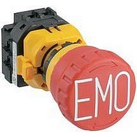
SWITCH, EMERGENCY STOP, 3NC/1NO, 250VAC
Manufacturer
IDEC
Datasheet
1.XA9Z-KG1.pdf
(8 pages)
Specifications of XA1E-BV413-RH-EMO
Contact Configuration
4PST-3NC / 1NO
Switch Operation
Pushlock Turn Reset
Contact Voltage Ac Nom
250V
Contact Voltage Dc Nom
250V
Contact Current Max
3A
Actuator Style
Mushroom
Lead Free Status / RoHS Status
Lead free / RoHS Compliant


SEMI S2-compliant Combinations
Note: Numbers in the circle refer to the pictures of the corresponding control units shown above.
About SEMI
SEMI is an international industry association whose member companies produce materials, equipment, and related technology for
manufacturing semiconductor, flat panel display (FPD), and micro-electromechanical systems (MEMS) products. The SEMI safety
guideline was published for the semiconductor industry and it is observed with the same importance as standards.
SEMI S2-0706, 12.1 describes as follows; “The equipment should have an ‘emergency off’ (EMO) circuit. The EMO actuator (e.g.,
button), when activated, should place the equipment into a safe shutdown condition, without generating any additional hazard to per-
sonnel or the facility.” Because the semiconductor environment involves solvents and chemicals in many cases, some of which are
toxic, interrupting the power source may cause secondary accidents. SEMI safety guideline requires the installation of an emergency
off switch which disconnects only the part responsible for the hazardous situation, and maintains the functions of safety-related
devices (e.g., smoke detectors, gas/water leak detectors, pressure measurement devices, etc.).
Emergency off buttons should be located or guarded to minimize accidental activation (SEMI S2-0706, 12.5.1). The emergency off
button should be red and mushroom shaped. A yellow background for the EMO should be provided (SEMI S2-0706, 12.3).
XA9Z-KG1
The combination of IDEC’s EMO switch guards and emergency stop switches are approved
by TÜV Rheinland for compliance with SEMI S2 standards.
SEMI S2 Compliant Switches / Switch Guards
2
EMO Switch Guard
• Location of EMO switches on semiconductor manufacturing equipment
• No operation or regularly scheduled maintenance location should require
Acceptance criteria: controls should not be located above 1638 mm (64.5 in.) or
below 838 mm (33 in.) (SEMI S8-0705, 9.1.2).
more than 3 m (10 feet) travel to an EMO button (S2-0706, 12.5.2).
EMO button
HW9Z-KG3
HW9Z-KG4
XA9Z-KG1
1
XA9Z-KG1
XA Series
+
3
(3 m maximum)
10
15
1
4
: XA1E-BV4 ∗∗∗∗ -EMO;
: XW1E-BV4 ∗∗∗∗ -EMO;
: XW1E-BV4 ∗∗∗∗ -EMO;
: HW1E-BV4, HW1B-LV4;
HW9Z-KG3
Operator
7
4
HW9Z-KG3
XW Series
(3 m maximum)
+
2
11
5
8
: XA1E-BV3, XA1E-LV3;
16
: XW1E-BV4, XW1E-LV4, XW1E-TV4;
: XW1E-BV4, XW1E-LV4, XW1E-TV4;
: HW1B-X4;
5
EMO button
17
Applicable Emergency Stop Switches
: HW1B-Y2
9
HW9Z-KG4
XW Series
6
3
: XA1E-BV4, XA1E-LV4
+
HW9Z-KG4
14
6
12
: HW1B-V3;
10
: XW1E-BV5;
15
7
: HW1B-V4;
1638 mm
maximum
13
: HW1B-V3;
11
838 mm
minimum
16
8
: HW1B-X4;
14
: HW1B-V4;
12
The combination of EMO
switch and switch guard
can be used with the FB
series control boxes.
For details, see the FB
series control box catalog
(EP1132).
17
9
: HW1B-Y2
13
3
Related parts for XA1E-BV413-RH-EMO
Image
Part Number
Description
Manufacturer
Datasheet
Request
R

Part Number:
Description:
SWITCH, EMERGENCY STOP, 3NC/1NO, 250VAC
Manufacturer:
IDEC
Datasheet:

Part Number:
Description:
Cable; Between IDEC MicroSmart (port 1 or 2) and HG2F/3F/4F; 5 ft.
Manufacturer:
IDEC Corporation
Datasheet:
Part Number:
Description:
Cable; Between IDEC Micro^3C/ONC/MicroSmart (port 2) PLCs and HG2F/3F/4F; 5 ft.
Manufacturer:
IDEC Corporation
Datasheet:
Part Number:
Description:
Angled Key for Idec HS6B Safety Switch
Manufacturer:
IDEC Corporation
Datasheet:
Part Number:
Description:
Accessory, L-Shaped Key for Idec HS5B and HS5E Safety Switch
Manufacturer:
IDEC Corporation
Datasheet:
Part Number:
Description:
Accessory, Straight Key for Idec HS5B and HS5E Safety Switch
Manufacturer:
IDEC Corporation
Datasheet:
Part Number:
Description:
Straight Key for Idec HS6B Safety Switch
Manufacturer:
IDEC Corporation
Datasheet:
Part Number:
Description:
LIGHT TOWER 3 TIER RED/AMBER/GREEN 24VAC/DC WALL MOUNT
Manufacturer:
IDEC Corporation
Datasheet:
Part Number:
Description:
Flat Lens, 24V AC/DC, 1m Cable Length, Alternate: Red Green Color, IP67
Manufacturer:
IDEC Corporation
Datasheet:
Part Number:
Description:
LIGHT TOWER 2 TIER RED/GREEN 24VAC/DC WALL MOUNT
Manufacturer:
IDEC Corporation
Datasheet:
Part Number:
Description:
INDICATOR INCANDESCENT LAMP, GREEN
Manufacturer:
IDEC
Datasheet:

Part Number:
Description:
LAMP, INDICATOR, INCAND, AMB
Manufacturer:
IDEC
Datasheet:
Part Number:
Description:
LAMP, INDICATOR, INCAND, GRN
Manufacturer:
IDEC
Datasheet:
Part Number:
Description:
LAMP, INDICATOR, INCAND, GRN
Manufacturer:
IDEC
Datasheet:
Part Number:
Description:
LAMP, INDICATOR, INCANDESCENT, RED
Manufacturer:
IDEC
Datasheet: