XA1E-BV313-R IDEC, XA1E-BV313-R Datasheet

SWITCH, EMERGENCY STOP, 1NO/3NC, 250VAC

XA1E-BV313-R

Manufacturer Part Number
XA1E-BV313-R
Description
SWITCH, EMERGENCY STOP, 1NO/3NC, 250VAC
Manufacturer
IDEC
Datasheet

Specifications of XA1E-BV313-R

Contact Configuration
4PST-3NC / 1NO
Switch Operation
Pushlock Reset/Push-Pull
Contact Voltage Ac Nom
250V
Contact Voltage Dc Nom
250V
Contact Current Max
3A
Actuator Style
Mushroom
Lead Free Status / RoHS Status
Lead free / RoHS Compliant
Switches & Pilot Devices
Key features:
Specifi cations
Applicable Standards
Operating Temperature
Operating Humidity
Storage Temperature
Operating Force
Minimum Force Required for
Direct Opening Action
Min Operator Stroke Required
for Direct Opening Action
Maximum Operator Stroke
Contact Resistance
Contact Material
Insulation Resistance
Impulse Withstand Voltage
Pollution Degree
Operation Frequency
Shock Resistance
Vibration Resistance
Mechanical Life
Electrical Life
Degree of Protection
Terminal Style
Recommended Tightening
Torque for Locking Ring
Wire Size
Soldering Conditions
Weight
Lead-free, RoHS compliant, (EU directive 2002/95/EC)
The depth behind the panel is only 27.9mm for 1 to 4 contacts,
illuminated and non-illuminated types.
IDEC’s original “Safe break action” ensures that the NC contacts open
when the contact block is detached from the operator.
1 to 4NC main contacts and 1NO monitor contact
Push-to-lock, Pull or Turn-to-reset operator
Direct opening action mechanism (IEC60947-5-5, 5.2, IEC60947-5-1,
Annex K)
Safety lock mechanism (IEC60947-5-5, 6.2)
Degree of protection IP65 (IEC60529)
Two button sizes: ø29 and ø40mm
UL, c-UL recognized. EN compliant
UL NISD2 category emergency stop button (File# E305148)
IEC60947-5-1, EN60947-5-1, IEC60947-5-5, EN60947-5-5
UL508, CSA C22.2 No. 14
Non-illuminated: –25 to +60°C (no freezing), Illuminated: –25 to +55°C (no freezing)
45 to 85% RH (no condensation)
–45 to +80°C
Push-to-lock: 10.5N
Pull-to-reset: 10N
Turn-to-reset: 0.16N·m
60N
4mm
4.5mm
50mΩ maximum (initial value)
Gold plated silver
100MΩ minimum (500V DC megger)
2.5kV
3 (inside LED unit: 2)
900 operations/hour
Operating extremes: 150m/s
Operating extremes: 10 to 500Hz, amplitude 0.35mm acceleration 50m/s
Damage limits: 10 to 500Hz, amplitude 0.35mm acceleration 50m/s
250,000 operations minimum
100,000 operations minimum, (250,000 operations minimum @ 24V AC/DC, 100mA)
IP65 (IEC60529)
Solder terminal, PC board terminal
0.88N·m
16 AWG max
310 to 350°C, 3 seconds maximum
ø29mm: 23g
ø40mm: 28g
USA: 800-262-IDEC
2
(15G), Damage limits: 1000m/s
16mm XA E-Stops
UL File No. E68691
Canada: 888-317-IDEC
2
(100G)
2
2
16mm XA E-Stops
CCC No. 2005010305150899
451

Related parts for XA1E-BV313-R

XA1E-BV313-R Summary of contents

Page 1

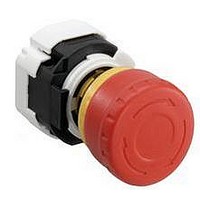
... The depth behind the panel is only 27.9mm for contacts, illuminated and non-illuminated types. • IDEC’s original “Safe break action” ensures that the NC contacts open when the contact block is detached from the operator. • 4NC main contacts and 1NO monitor contact • ...

Page 2

... Switches & Pilot Devices Part Number XA1E-BV311V-R XA1E-BV302V-R XA1E-BV313V-R XA1E-BV304V-R XA1E-BV311-R XA1E-BV302-R XA1E-BV313-R XA1E-BV304-R XA1E-BV411V-R XA1E-BV402V-R XA1E-BV413V-R XA1E-BV404V-R XA1E-BV411-R XA1E-BV402-R XA1E-BV413-R XA1E-BV404-R Part Number XA1E-LV311Q4V-R XA1E-LV302Q4V-R XA1E-LV313Q4V-R XA1E-LV304Q4V-R XA1E-LV311Q4-R XA1E-LV302Q4-R XA1E-LV313Q4-R ...

Page 3

... Panel Cutout – 1.2A 0.6A +0.2 – 0.6A 0.3A 1.7 2A 0.4A 0.2A 1A 0.22A 0.1A PC Board Layout - Bottom View Non-Illuminated 19.8 8.7 6.5 Part Number Key XA1E - Illumination B: Non-Illuminated L: Illuminated Mushroom Size 3: ø29mm 4: ø40mm 2NC 1NO-1NC TOP TOP Left Right Left ...

Page 4

... Mushroom Size HAAV-0 16mm 43mm 29mm HAAV-27 16mm 43mm HAAV4-0 16mm 60mm 40mm HAAV4-27 16mm 60mm www.idec.com Switches & Pilot Devices Illuminated Mounting Panel Thickness: 0.5 to 3.7 Rubber Gasket Locking Ring 29.4 Terminal Cover XA9Z-VL2 20.6 25.8 2.1 3.1 30.4 PC Board Terminal Solder Terminal 20 ...

Page 5

... TOP side Installing the LED Unit Align the top of the LED unit with the TOP marking on the contact block. Push the LED unit into the contact block. Locked USA: 800-262-IDEC Canada: 888-317-IDEC 16mm XA E-Stops TOP marking k Turn j Press TOP marking (contact block) Squeeze the LED unit on the latches and pull out ...

Page 6

... Surface for installing components All dimensions in mm. • Use wires of the proper size to meet the voltage and current requirements, and solder the wires correctly. If soldering is incomplete, the wire may heat during operation, causing a fi re hazard. www.idec.com Switches & Pilot Devices Projection Nameplate ...

Related keywords